SICK Robot Day 2014
delivery of wooden cubes
This year autonomous robots were delivering wooden cubes (a printed barcode defined the target location). Up to four robots were competing at the same time. There were 15 teams competing. How it went? See the compilation of the best teams … Update: 21/10 — Photos (Standa)


This article is a compilation of contributions from several participating
teams. The content may evolve with the time, as new texts will arrive or some
parts will be translated cs<->en. Please note, that currently the Czech and
English version are very different! The Czech version
(Google
translation … it looks like Google is giving up in the middle) primarily
contains blog about Eduro Team preparation, so it is much longer.
Content
- 1st place: PARMA (6 points (+5))
- 2nd place: Attempto (6 points (+3))
- 3rd place: Deep Cube Osnabrück (3 points)
- 4th place: Eduro (2 points)
- 5th place: eXception München (1 point)
- Photos
Note, that all other teams did not finish with a positive score.
1st place: PARMA Team, Parma
PARMA (Personal Autonomous Robot for Mobile Applications) Team
International competition for mobile robot. The challenge is organized by SICK AG and RIMLab took part in
2010 and
2012, and won the latter. This year
robotic race is a kind of mailman race. The arena is a convex bullpen of about
13 x 13 meters, which contains an "island" in the middle with the filling
stations. At each round four robots receive a wooden cube with a bar code from
a filling station. The bar code gives the number of the goal stations to reach.
The more goal stations are correctly visited in the given time (10 minutes),
the higher is the team score. Of course, the robots must avoid collision with
other robots and the border of the arena. For more information see
Robot
Day general rule. The event took place on Saturday October 11th 2014 in the
Stadthalle in Waldkirch (Germany). PARMA (Personal Autonomous Robot for
Mobile Applications) from the University of Parma won the competition
delivering 5 cubes in the first run and 6 cubes in the second one.
First Run
Second Run
Robot Hardware: Actuators and Sensors
The robot is a
MobileRobots
Pioneer 3DX
provided with a basket to carry the wooden cubes as required by
the competition. The basket has the shape of a funnel to bring the cubes to
its center.

The basket contains two kinds of sensors to read the barcodes placed on the
faces of the cubes: a
Sick
ICR803-B and two
Logitech C270 USB
cameras. Sensor ICR803 is positioned to keep the proper distance from the
center of the cube (about 10 cm). The USB cameras provide a redundant cube
detection system based on a computer vision library to read barcodes
(zbar library). A LED is placed inside the
basket to light up the cube and a green one to signal that the robot is ready
to receive or deliver. The LEDs and the interface with Sick ICR803-B are
controlled by an Arduino One board.
The robot is also equipped with a
Sick
LMS100 laser scanner and a
Point Grey
Bumblebee XB3 part of Vislab
3DV Stereo Vision. The LMS100 laser scanner is the reliable and robust
sensor that allows obstacle detection and navigation. The 3DV stereo vision
system provides the left and right images, the disparity map and the 3D point
cloud obtained by stereo processing. Unfortunately, there was not enough time
to develop algorithms for 3D processing (e.g. to estimate the 3D poses of
numbered plates).
Computer Vision Perception
|
The computer vision is used to detect numbered plates and targets. Number
plates are the labels of goal stations. The targets are placed in front of
each filling and goal station. Like for many computer vision methods, the
developed algorithm initially search the regions of interest (ROI) and, then,
performs classification and tracking. First, the ROIs are found by extracting
lines (using EDLines algorithm) and rectangles from each frame. Second, in the
case of plates, the content of the ROI is classified by a trained Artificial
Neural Network (ANN) according to the OCR histogram of the rectified ROI. In
the case of targets, the detector searches circles, lines and their
intersection points.
The pose of plates and targets is estimated using the projective geometry and
the information on their size. Furthermore, the estimated poses (i.e. the
projection in the scan plane) are validated by the laser scanner. A pose is
valid only if its projection corresponds to an obstacle.
Navigation
The navigation module manages the mission state, the path planning and the robot motion.
It consists of several subtasks.
- Local Planner. The local planner builds a local occupancy grid map using the measurements from the laser scanner and inflates the obstacles. Given the goal pose (e.g. a pose in front of a numbered plate or of a filling station), the planner computes a trajectory on the occupancy grid map according to a graph search algorithm (tested algorithms: Generalized Voronoi Disgram, A*, D*).
- SLAM Module. The SLAM module builds a map of the environment consisting of the robot poses and of the numbered plates used as landmarks, and iteratively updates the estimation of robot pose w.r.t. the initial reference frame. The odometry and vision measurements are integrated into the Graph SLAM framework g2o. This modules provides the goals (the filling and goal stations) to the planner.
- Approach Task. The approach module allows the robot to reach its goal (a filling or goal station) aligned with the arena fence. It exploits the observation of the targets in the image.
The following video illustrates how the modules work together with a simulation
(the simulator is Gazebo, integrated in ROS).
PARMA team, winner of Sick Robot Day 2014!

Front from left to right: Fabrizio Castelli (Sick Italia), Fracesco Valenti,
Marco Pedretti, Marco Paini. Back from left ro right: Cecilia Bollati (Sick
Italia), Marco Allodi, Fabjan
Kallasi, Domenico Giaquinto,
Dario Lodi Rizzini.
Questions & Answers
Where there any failures of your robot during competition?
The main failures we observed are related to the recognition of filling station
state. Actually, the robot checked whether the filling station is occupied by
another robot by assuming that the filling station fence appear like a segment
when observed by the laser scanner. Furthermore, such segment must lie close to
the expected position of the filling station (from the map). In the end of
second run, it seems that free filling station detection is difficult. We
suppose that two things can have influenced such behavior.
1) We expected a square island in the middle of the arena (the rule of
procedure is somehow ambiguous: They are located at the 4 sides of a square
island
(en-rules)
and instead it was octagonal. Of course, we adapted thresholds, but the initial
assumption has an impact on the algorithm design.
2) The pose of filling stations is not updated by the mapping module, but it is
initially set. The map contains only robot and numbered plates poses (with the
constraints given by odometry measurements). Hence, an error in robot pose
estimation (that, in spite of SLAM, increases a bit) can affect the decision on
busy/free state.
Any other surprises?
Another surprise was the limited number of goal stations: only 4, we expected
8. This low number increased traffic and competition for stations. This was a
problem at least in our first run.
How did you detect the navigation target?
There are slightly different algorithms to detect numbered plates and targets.
- Numbered plates: detection relies on rectangle detection and, then, the inside is classified by a trained ANN on histogram.
- Targets: detection exploits circle detection (at different scales, to make it more robust).
The pose of the two target is estimated through perspective geometry
(mono-camera estimation, not stereo!) since the size of the two items is known
(see solvePnP() in OpenCV). In both cases, the laser validation is required.
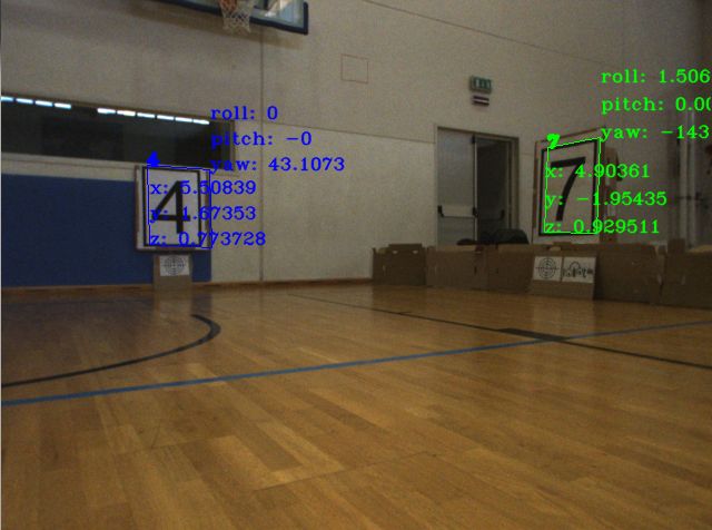
The numbered plates are detected by vision also from 12 m if no occlusion
occurs, but since laser validation is required to accept it the full detection
occurs when the robot is closer to the plate. Of course, the estimation only
with vision is noisy in particular for the orientation of the plates (the yaw
angle changed also of 20 deg between two observations!). Thus, a proper
tracking was added.
We had a problem (never observed in our month-long trials in Parma!) during the
trials in the morning. One of the windows with a sloopy roof was similar to
plate with number 4 and its size was compatible with the distance of the
filling station fence. We added a constrain: to be accepted a number must lie
on the external fence. This solved the problem and, then, they closed the
curtains in the afternoon.
2nd place: Attempto Tübingen
This year we were able to continue our successful participation at the SICK
robot day, placing second out of 14 teams from Germany, the Czech Republic,
England and Italy. The competition was again organized by SICK AG in Waldkirch
near Freiburg, Germany.
The task
This year's task was to collect cubes at a collection station at the center of
a circular arena. These cubes were labeled with barcodes, which represented
one of four delivery stations at the outer border. These deliveries were
marked with the same signs already in use back in 2010. The robot got one
point for every correctly delivered cube, and one negative point for each wrong
delivery.
Our robot was able to deliver 6 cubes in 10 minutes in the first round, just as
many as the winning team PARMA delivered in their better run. In the second
run we had a hardware problem, leading to a 5 minute pause in which our robot
did not move at all. Afterwards the robot was able to collect a few cubes, but
not enough to achieve the first place.


Our approach
Our robots Arnie and Sly are based on a former, omnidirectional RoboCup
robot that has attended the SICK robot day twice in the past. They were heavily
revised in order to meet the requirements for the tasks of this year's event.
The most important revision was to make the robots as low as possible to be
able to drive under the pick up and delivery rings.
A combination of multiple methods was implemented to solve the sign and target
detection problem. These includes artificial neuronal network based machine
learning methods as well as Hough line detection. Furthermore we implemented a
RANSAC based map analysis to detect the central area, which was supposed to be
square, but ended up being an octagon.
We used a customized version of slam_karto
for localization and mapping, which was optimized for faster grid map
generation. Furthermore we employed laser scan segmenation to only map long
segments for a more robust system. Path planning was done using A* with an
omnidirectional motion model and path following was implemented using
orthogonal projection and an exponential law.
Team Attempto
Attempto Tübingen is a team of students and faculty staff with background in
Computer Science, Bioinformatics, Automation, Control and Cognitive Science.
Our two robots Arnie and Sly are based on former RoboCup models that have
attended SICK Robot Day twice.

Team Members
- Sebastian Buck (sebastian.buck at uni-tuebingen.de)
- Richard Hanten (richard.hanten at uni-tuebingen.de)
- Goran Huskić (goran.huskic at uni-tuebingen.de)
- Alina Kloss
- Jan Leininger
- Gerald Rauscher (gerald.rauscher at uni-tuebingen.de)
- Eugen Ruff
- Felix Widmaier
More information
Questions & Answers
Failures?
- Waiting times were too long. We waited the full 10 seconds at delivery and pick up stations. We had to wait for ~6 seconds every time we were approaching a target sign.
- In the second run we had a spurious measurement of our main laser scanner which reported an obstacle directly in front of our robot, which caused a 5 minute long pause.
Surprises?
- The rules stated that the central area was square, so we used this knowledge to find the four pick-up stations. On site we had to rewrite this central part of our system to detect an octagon instead of a square and to decide, which four sides of the octagon were equipped with a station and which not.
How did you detect navigation targets (Zielscheibe)?
First we projected the front laser scan onto the image to mask out everything
but the border plane in which the targets where positionend. Further masking
was performed using morphological gradients to detect regions of interest.
Then we performed Canny line detection and the Hough Transform on these ROIs to
find vertical and horizontal lines and looked for the crossing point, the
circles / ellipses were totally ignored. We then used the camera calibration
matrices in combination with the projected laser scan to determine the pose of
the target. The poses were averaged over a few measurements, which was not
that efficient (especially on our Core2Duo CPU) and caused the waiting
pauses.
4th place: Eduro Team, Praha
Robot Eduro participated on SICK Robot Day already in
2010 and
2012. This was an advantage, because we
already know how difficult the contest is and we had some idea what troubles we
can expect .
Robot
Eduro is already proven prototype platform with proprietary SMAC (Stepper Motor
— Adaptive Control) motors, CAN bus, a single board x86-based computer
running Linux OS (AMD Geode CPU/500MHz, 256 MB RAM, compact flash card, Wi-Fi,
3 Ethernet, 1 RS232 and 2 USB ports) and it is powered by two 12V/8Ah sealed
lead acid batteries.
Eduro is equipped with CCTV IP camera with with fish-eye lens. Since 2010 it
has also laser scanner LMS100, thanks to SICK. You can find more about the
platform in the
Robotour 2010
proceedings.
There was an extra bar code reader attached to USB port for this contest.
Software
The software is written mostly in Python and some parts, like image processing,
are written in C/C++ (using OpenCV library). The source code is freely available at:
Version 0
I think that concept of „version 0” can be dated back to
Eurobot contest where robots had to pass
homologation i.e. score at least one point without opponent robot. It is
the simplest thing that could possibly work, i.e.
eXtreme programming in
robotics. If you have ver0 you can relax a little bit — you have something
working. You can also start to collect data and see what bits
are the real problem and where improvement is needed. And if everything goes wrong you still
have something to compete with .
For SICK Robot Day 2014 this meant delivery of one cube. Well, 24 hours
before the contest we did not have tested algorithm what could be called version
0…
Target recognition

The main difference (when compared to 2010 contest) were navigation targets and missing columns with numbers.
This algorithm was critical because without that
Eduro failed to collect a cube.
The recognition of numbers (see bellow) is based on contours extracted from
thresholded image. It was necessary to use the same concept to reduce
computational requirements.
The idea was to look for a contour containing twelve smaller contours. Because
black lines are relatively thin it was necessary to erode image by 3x3 kernel
(see Python version
recognizeNavTarget()
for details).
We had to add some constrains for these 12 small contours to limit the number
of false detections. There were surprises like for example the area of the
bigger arc does not have to be bigger then area of inner arcs (it should be
mathematically but sometimes it fails in reality). Minimal bounding
rectangles were used instead and „area” was then estimated from their size.
And that worked fine.
The rejection rule was that 4 biggest sub-contours have to be in the four
corners and then next 4 biggest sub-contours have to be again in all four
corners. This was even fun to watch: see
video — frames with detected
target are 10 times slower and once a while you can see „random colors” which
are 1+12 contours groups failing to fulfill the criteria.
Digits recognition
The recognition of digits did not work very well in 2010 — in particular I still see
the image of rObOt day poster where two letters 'O' were connected and Eduro
classified that as digit '8'. The old algorithm expected first to detect the
frame and then only decided what is the content, but … there were really
bad light conditions in 2010 and plate frames just „disappeared”.
The 2014 code was very similar to the one in 2010. Note, that there was also an
experimental solution on parallel RaspberryPi which I refused to integrate at
the very end as „not sufficiently tested”. On the way to Germany (approx. 12
hours drive due to many traffic jams) this code was revised so that it could
work even without the frames. We needed high reliability of detection so we limited
the size of numbers to really big, the height and position in the image had to
be in given proportions, and we re-introduced frame detection. Image erosion
needed by target recognition also helped with frame detection.


Results

The contest for us was really the fight for the 3rd place (and the winners of
2010 and 2012 would split the first and second place). Eduro expected stright
wall near the navigation target, and that sometimes failed for used octagon.

Because Eduro is not omni-directional robot, and image frames were approx. at
1Hz with 1s delay the idea was to get 40cm from the wall with laser feedback
and turn towards the target (processed camera). Eduro has very precise odometry
so it is capable to turn by desired angle and backup.
While during the tests at home we sometimes had problem detect target even at
50cm in Waldkirch it worked from 2 meters! Pickup worked in 4 of 4 attempts, but
the problems were near the goal.
The first problem was that there was an obsolete code using angles instead of
absolute position for approaching numbers from close distance.
The second major problem was missing verification if robot is heading towards
island or border causing infinite shaking in order to recognize non existing
cube.
Thanks to „blocking rule” we were allowed to restart Eduro and collect two
cubes in each run. In the second run we re-entered the same feeder and got
minus point for that. In total we finished on shared 4th place which I would
still consider a success .
Questions & Answers
How did you solve the non-square center problem?
Well, we did not. The pickup of the first cube was without any problem and for the next
cubes we tried to navigate to the center of the „occupied area in the
middle”. There was a backup to go around the island if the target was not
recognized and that would work for both octagonal as well as square.
Verification that nearest reading is from perpendicular obstacle was not added at the
end.
Photo (Stanislav Petrásek)


 repeated mistake")


If you have any question or comment (including questions to presented teams) —
contact us.