SICK Robot Day 2016
the die is cast
Another „SICK Robot Day” is over. This time two robots had to place cubes in the field loaded with RFID chips in 5x5 meter bit „chess” area. Once the cubes were placed then they become obstacle and future collisions were penalized. So how it went?
Rules in nutshell
The playing field has size approximately 7x13m. Two autonomous robots start
from yellow and ping 3x3m storage area. Their task is to delivery cubes to the
central 5x5m large playing field. The cubes have to be carried separately and
robots get points for each covered 1x1m square. The point is gained by robot,
which places the cube on given square as first one. As soon as the cube is
placed it automatically becomes an obstacle (for both robots) and contact is
penalized by lost of 0.5 point.

|
The match takes 10 minutes and every team plays two matches. The color and the
oponent are randomly selected. There is RFID chip on every crossing of the
field to simplify robot navigation. The code defines (X, Y) coordinates but
also the „zone type”. The organizer provided teams sensors
RFU
620, and the data are available over the Ethernet or CAN bus.
Results
| Team | Lauf 1 | Lauf 2 | Bestes | Platz |
|---|---|---|---|---|
| Karlsuni Prag | 7.0 | 6.0 | 7.0 | 1 |
| Uni FR | -0.5 | 5.0 | 5.0 | 2 |
| EDURO | 2.0 | 4.5 | 4.5 | 3 |
| Kamaro Engineering e.V. | 4.0 | 4.0 | 4.0 | 4 |
| Osnabrück | 1.0 | 2.5 | 2.5 | 6 |
| FRED | X | 1.0 | 1.0 | 6 |
| Alpaca | 0.0 | 0.0 | 0.0 | 7 |
| WINGmen | X | X | 0.0 | 7 |
| Smelý Zajko | - | - | - | - |
Cogito MART (1st place)
The winner of SICK Robot Day 2016 is team Cogito MART. You can read
interesting
Cogito diary how the robot named Clementine was modified for the contest
12 days to the competition.
CS Freiburg (2nd place)
author: Andreas Hertle
Our robot is called Zerg based on a speedy unit (Zergling) from the strategy
game Starcraft. The robot was built in 2005/2006 for a race competition, thus
high velocity and acceleration are its dominant attributes.
As robotic middleware we use ROS running on Ubuntu, which for us has two major
benefits:

1. The ROS community provides a whole range of ready-to-use components, ranging
from drivers for various sensors to path planning and perception libraries.
Thus less time needs to be invested into the development of components not
specific to the task at hand.
2. The flexible communication between ROS programs allows for easy
re-configuration of the system. Multiple alternative implementations of
specific components can be prepared in advance and quickly exchanged should one
show significant advantages.
This year we upgraded the electronics hardware, replacing the old custom built
boards with an Arduino Mega. The Arduino program reads the wheel encoders to
estimate the current velocity and feeds it to the PID controller for the
motors. Our robot can reach a linear velocity of 2.3 m/s, however there is
rarely enough free space to utilize maximum velocity. For turning the robot
relies on skid steering. In theory it can turn 360° in half a second, however
that is much faster than the navigation algorithms can handle. For the
competition the linear velocity was limited to more manageable 1.3 m/s and the
angular to 180°/s.
Gripper

|
To move the foam cubes, we constructed a specialized gripper. It has a round
shape so that the cubes do not need to be aligned and can be picked up at an
angle. Usually at the front of the robot we put our laser range finder and to
be able to see the cubes the laser sensor had to be placed less than 0.15m
above ground. A solid grip can be achieved when holding the cubes equatorial,
so 0.075m above ground. Furthermore, the gripper should block as few laser
beams as possible in both the lowered and raised state. That is the reason for
the arcing shape of the arm: the laser sensor is placed at the center.
The gripper was designed with Blender and printed on the MakerBot Replicator
5th generation. We use one Dynamixel AX12-a servos to operate the closing
mechanism and two to operate the lifting mechanism. Finally, we attached a Sick
WT4-2P132 distance sensor to detect whether the gripper is holding a cube.
Cube Perception
Since this year’s competition focuses on transporting foam cubes, perceiving
those cubes reliably is a key component. We implemented two different
approaches.
The first relies on 3d point cloud data, as produced by a Microsoft Kinect
camera. In the first step the ground plane is detected and removed from the
point cloud data, also points above cube size are removed. The remaining data
is segmented by distance to separate individual cubes. Region growing
algorithms find the visible sides of each cube. With this data the center and
orientation of the cube can be computed. The point cloud also contains color
data, thus the color of the cube can be determined. Unfortunately this whole
process is computationally expensive. Even after subsampling the input data the
algorithm requires 1 second to process a point cloud. Furthermore, the small
horizontal angle (48°) of the Kinect camera and the minimum distance of 0.5m
complicates the problem further.
Thus we implemented an alternative approach based on data from a laser range
finder. The laser data first is segmented based on distance between two
neighbouring ranges. Then we determine which point cluster are fully visible
(not occluded by their neighbouring clusters). Finally, the distance between
the first and last point decides whether it is a cube or something else. We can
not determine the color of cube, however, the color information does not
influence the behavior algorithms anyway. With this algorithm we can detect
cubes in a 200° cone and between 0.05m and 10m as fast as the laser sensor
produces the data (40Hz).
RFID Localization
The second half of the challenge for this competition consisted of recognizing
RFID tags in the environment to distinguish the score fields and the home base
field.
We modeled the location of the RFID tags as a second map layer. The first map
is produced by the laser range finder. We estimate the displacement between the
origin of the laser map and the rfid map with a probabilistic particle filter,
similar as is done in Monte-Carlo Localization. The challenging part here was
modeling the RFID sensor: the sensor produces the tag id and signal strength,
which localizes the robot in a radius of up to 0.3m around that specific tag,
so it is not very precise and has no orientation. Unfortunately we did not
manage get the particle filter working reliably in time for the competition.
Thus, we went for an easier but less reliable method: we rely on the assumption
that the enclosing fence is placed symmetrically around the RFID tags. That is
the center of the enclosed area coincides with the center of the RFID map. We
take the free cells in the laser map as input and compute the mean and
covariance. With a Singular Value Decomposition we get the main axes and the
center of the environment. Thus, we can estimate the center of the RFID map
based solely on laser data.
Behavior
We encoded the behavior of the robot as a deterministic state machine. The
process of placing cubes consists of the following steps:
- Navigate to a random pose around the home field if no cube is detected.
- Navigate to closest cube in the home field.
- Lower gripper, approach cube and pick it up.
- Decide where to place the cube.
- Navigate to target field.
- Lower gripper and release cube.
Should the cube sensor in the gripper report that no cube is in the gripper,
the algorithm jumps to the appropriate state (1, 2 or 3 depending on the
distance to possibly visible cubes).
|
The strategy is implemented in step 4. We prepared two alternatives: the
aggressive strategy selects target fields closer to the opponent's home field;
the defensive strategy places cubes closer to our own home field. In the
competition our robot was using the defensive strategy.
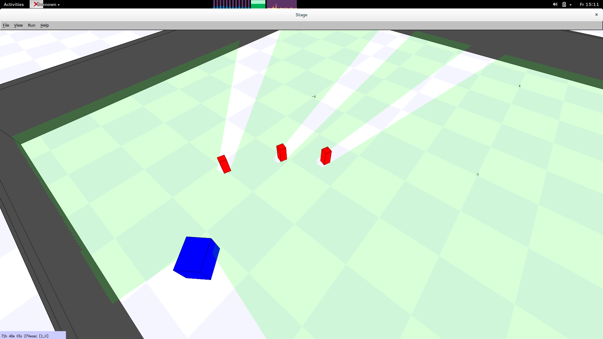
A simulator was crucial during the development of the overall behavior, since
we did not have the room to physically build the whole playing field in our
lab. We used the Stage simulator, which simulates (mostly) in 2d and is
lightweight, so that multiple robots can be simulated. The blue box in the
picture represents the robot and the red boxes the cubes. The field of view of
the laser sensor is displayed in green.
Challenges during the competition

After arriving at the Stadthalle, we soon realized that something was wrong
with the robot’s main sensor, a Hokuyo UTM-30LX laser range finder. The sensor,
which was working fine in our lab, kept crashing every few minutes. We figured
out, that the sensor detected other infrared light sources and determined that
turning itself off was the sensible thing to do. So we spent most of the
preparation time getting a replacement sensor from our lab (home advantage) and
mounting it on the robot. The only sensor we could get to work in the short
time was a Hokuyo URG-4LX (4m max range), which is a huge downgrade from the
UTM-30LX (30m max range). We assume the reduced range is to blame for failure
in our first run.
We were so focussed on the problems with the laser sensor that we did not
figured out the second problem before our second run: the carpet. Our robot has
skid-steering but the carpet had high friction which made fine turns all but
impossible.This can be observed when the robot tries to approach a target field
or approach a cube. Not sure if we could have done anything about it, maybe
wrap the robot’s rubber wheels in tape. Fortunately, our luck was that the
sharp turn and stop maneuvers shook free the cube the robot was carrying and
the cubes even rolled on empty target fields!
Additional thanks to students who did not participate in the competition but
worked on components in previous semesters: Robert Grönsfeld, Natalie Prange
and Hermann Ritzenthaler
EDURO Team (3rd place)
There is EDURO Team Diary when you switch this page into Czech. Hopefully
there will be enough energy to create short English summary later on, but for
now enjoy the videos from David/MART. See his complete
SICK Robot Day 2016 video list.
Eduro "show time"
… the most cubes were placed in the very last game (not counted for Eduro)