Berta
vacuum cleaner controlled by microcontroller
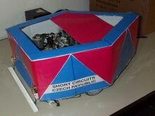
Berta is the winner of the Cleaning contest 2002! It is the prove that the simplest solutions are often the best. It has beaten its competitors with 2D range finders, cameras and a lot of processing power simply because it worked the way it was supposed to using only a front bumper and a microcontroller. Find out how eXtreme programming concepts work while building a robot.
Quick Info
The boggie is made of aluminum U-shaped profiles, powered by two DC motors
(1.5Amp/12VDC, 5500rpm with 20:1 gearbox). The brain
of the robot is 16bit Hitachi microcotroller (14.745 MHz clock, 4kB RAM, 128kB
ROM (flash)). The only sensor that this robot utilizes is its front bumper.
The cleaning method is based on a random walk algorithm.
Mechanical Design
The boggie is made of U-shaped aluminum profiles. Aluminum has proven itself
to be a relatively light and quite durable material for such a construction.
The bogie is a triangle with two geared motors mounted in the base, which is also
front of the robot. The opposite vertex provides support for a caster wheel.
The motors are 1.5Amp/12VDC, 5500rpm with 20:1 gearbox (dimensions: 60 x 33 x 33mm).
The cleaning unit is a plastic box made with a hot-glue. The box is
removable and it is attached to the robot by aluminum holder. Dry vacuuming is
used for collection of dirt. The cleaning mechanism consists of 2 salvaged 12V
car vacuum cleaners and a box for collecting the dirt, equipped with 2 nozzles.
An additional brush helps to collect dirt before it is sucked into the box.
The power source for all motors and electronics is 12V 7AH/20AH sealed
rechargeable lead battery.
Both motors are powered by dual H-bridge and controlled via PWM (Pulse Width
Modulation) directly from the main microcontroller. A feedback is provided by two
encoders taken from a regular computer mouse. A non-linear PID controller is
used for maintaining speed and direction.
Onboard Computer
Single microcontroller Hitachi H8/3048 - 14.745 MHz clock, 4kB RAM, 128kB ROM
(flash). During software development we have found, that it is more convenient
to drive robot as a slave from a PC through a serial interface. The H8 processor
was programmed to fulfill the simplest tasks only and the program itself run in
the PC. The PC allowed precise logging and easier changes in program. The same
program was programmed to the H8 chip only after the software development was
finished.
Sensor System
There are only two means of sensing the environment for the robot:
- bumper micro-switches
- virtual bumper based on correlation between applied power to the motors and resulting speed measured by encoders
The switches are very reliable and do not need any filtering. There are
scanned every millisecond in the main processing loop where the change of state can
be directly triggered.
The virtual bumper exploits the fact that the motors are not that powerful.
If the maximum power (100% duty cycle of PWM) is applied to the motors for 1.5
second and robot is not moving then collision is registered. Again, this
detection has proven to be quite reliable given the combination of the robot
weight and motor power. From the view of the higher control software collision
detected by the virtual bumper is indistinguishable from regular collision
triggered by a micro-switch.
Obstacle Avoidance and Navigation Strategy
The obstacle avoidance is very simple, because a random walk (our coverage
principle) does not require precise realization of the plan. When collision
occurrs robot tries to roll-back its last action. If it collides while moving
forward, it backs up 25cm and turns left or right for given value. The values
are precomputed and stored in a table. If it collids while turning, it
returns to its original position (the robot always turns on a spot), and
backs up another 25cm. The last case, when the robot collids while reversing
is not properly handled. It tries to turn, but better solution would be (based
on experience in Lausanne)
move forward say 10cm, and try to turn some smaller
“escape” angle.
Coverage Principle
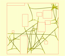
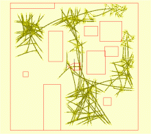
The presented strategy during the cleaning contest was a "random" walk.
The rules were created by random generator, but for actual run they were coded
into a table. Each command was defined distance how far should robot move
straight and how much it should turn (with a sign determining direction
left/right). This strategy was chosen for its simplicity and robustness (taken
into account the environment and sensors used).
Performance Data
The performance was measured separately for cleaning, obstacle avoidance and
for coverage:
The test track for cleaning was on linoleum floor covered with confetti and
sugar. The nozzles and the brush were then adjusted according to the immediate
results.
The obstacle avoidance was tested in normal office environment - chairs,
tables, cables on the floor. It showed that simple bar with two micro-switches
as a sensitive bumper is quite sufficient for given task. The maximum speed and
position of the bumper was tuned during these experiments.
The coverage was tested only under simulation. The main control loop was
called 600000 times (10 minutes, 1ms cycle), and coverage ratio was based on the
number of squares visited by robot. This was not perfect evaluation, but it was
a good indicator if the strategy is getting better or worse.
| Martin Dlouhý (md) | team leader, SW, testing |
| Jan Hradil (jh) | HW, brushes, pizza box |
| Mike Hibbett (mike) | vacuuming box |
| Ludvík Tesař (lt) | HW, brushes, pizza box |
| Jana Halgašová (jana) | surface finish, presentation |


