Ferda a Fatima
Merkur robots for Eurobot 2005
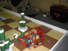
Ferda and Fatima is a pair of simple robots controlled by microcontroller ATmega8. Our goal was to show that even with very simple electronics and mechanics (Merkur construction set, a czech version of Meccano) it is possible to participate in the Eurobot competition. It is also an example how your first robot could look like if you plan to start with robotics.
Motivation
It was a relatively log time ago when we discussed the possibility of a robotics
construction set with Ing. Radko Kříž from the Cross company. According to our
readers a lot of them would welcome such a set. Unfortunately we are not any closer
to that goal then we were at the start…
Ferda and Fatima are the examples of how we could approach such a construction set.
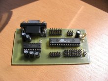
Both robots are controlled by a simple board with ATmeg8 controller (it is the same
board as in i.e. robot Faethon). You can either build it yourself
or get in touch with us and we'll work something out. The robots are powered by
servo motors modified for continuous revolution. The rest is only the Merkur
construction set (mine is number 5 and it is still alive — the movie
Short Circuits that gave the name to our team is in Czech called „Number 5
is still alive”).
Eurobot 2005
As we already said F+F were built for the Eurobot 2005
competition. Ferda's task was to find the bridge and cross it without returning
back to the starting half of the field and move randomly to knock down some
skittles. Fatima was at the end given much simpler task. It is worth to note
that that she went through many reincarnations as you can see on the pictures —
that is one of the advantages of using a construction set when you can build
a completely different robot within an hour . Her task was to defend
our skittles. The last version of her control program waited for the starting
cable to be pulled out, counted 2s to give Ferda enough time to move out
of the way, then 14.4s go almost straight and stop — simply no AI.
Like it or not, I have to admit that F+F didn't gain that many points for
Short Circuits this year. Ferda certainly missed some unfolding mechanism
that would allow him to knock more skittles. Even though he's found the bridge
and crossed it in each of the matches, it sometimes happened that he didn't
hit even a single skittle. Some simple spring could have been enough.
Fatima did not do anything wrong, but she did not do almost anything.
Mechanics and Gear Placement
One of our motivations was to experiment with different gear placement than
so far. All of our robots we have made so far are differentially driven. They
have to motors, one for the right wheel/track, other for the left. Ferda, and
also several versions of Fatima, had only one driven wheel that could also be
turned to change direction. It probably bears the most similarities with for-lift
truck. The MART team has commented on this: „It's an interesting idea but it
is absolutely not appropriate for Eurobot”. Well, it is not. But we've gained
some experience with it (Jiří Iša has built Ferda, I've built Fatima) that might
eventually come handy
The advantage of the one-wheel design is that it is relatively easy
to go straight or on a curve of a given curvature. The disadvantage,
a rather fundamental one for the competition, is bad manoeuvrability
and worse performance (instead of two motors you have only one).
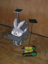
Ferda stayed close to the original design (we've only changed front
for back and took the face of the rabbit). Fatima at the end metamorphosed
into a classical tank vehicle with treads powered only by one servo motor.
Despite that she was able to cross the ditch or knock down some skittles
(going straight was more than enough for a robot-defender).
Sensors
To fulfill the objective of Ferda and Fatima a small number of sensors was needed.
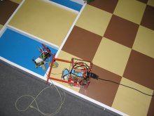
Beside front bumper (microswitch with a rubber band) was Ferda equipped
with several CNY70 sensors. They were used to detect the ditch (almost no
return IR signal) and the white line. Another two sensors were used for
the free running right and left wheels where they fulfilled the function
of encoders. We also wouldn't leave out our favorite virtual bumper,
i.e. when the powered wheel is turning but the encoders on the free running
wheels do not change, it is very likely that the robot has collided with
something.
ATmega8 Board
Both robot were controlled by ATmega8 board. The software development
was divided into two phases. First the robot was controlled from a notebook
computer using a serial cable. Only after everything was working was the
software programmed into the chip itself. I have to admit that I've become
spoiled over the years so the next time I would not go as low. When working
with something like the iPAQ there is more room and there is
always a log of all the tests which we missed deeply on the bare chip. On the
other hand the resulting robot is completely autonomous and you can build several
of them really cheap .
ATmega8 controller is quite cheap (you can buy it in GM Electronics
for 70Kč) but can do most things a roboteer needs. It has got serial communication,
timers, 6 analog inputs, internal oscillator up to 8MHz, ISP for easy programming etc.
It is probably a bit more sensitive to operator errors than i.e. AT90S8535
that we've used in Daisy, because we (and our students) have
burned several of them :-(.
The board we've designed is really simple. It just takes all the pins and it
makes them easily accessible. Adding MAX232 to support serial communication
with the RS232 port and several LEDs (power, heart-beat, serialIn, serialOut).
Eight outputs are grouped with ground and external power line to directly support
the control of up to eight servo motors. Also all of the analog inputs are
paired with a reference voltage and ground for easy connection of the
sensors or maybe potentiometer. We have left only the ISP connector and
couple of digital inputs.
All of the I/O pins are configurable either as input or output so it is
not necessary to always use all 8 servos or 6 analog inputs. For robot
Faethon we've used only „servo outputs” to receive
signal from the RC receiver. Analog inputs 4 and 5 can be used for I2C communication
thus interconnect several of the boards. But that is more of a distant future…
Programming
The board is fairly universal but the software is a bit more intricate. We've
used the same interface involving an input and an output structure to shield
from the implementation details. That is useful mainly during the first phase
of development when all commands (and sensor information) are sent to (from)
the chip over the wire from (to) the PC. The code running on the PC can then be
compiled for ATmega8 and run directly on chip (presuming that it is small
enough and does not require floating point operations).
To transfer the code compiled on the PC we've used the parallel port and
a simple programming device consisting of a couple resistors. ATmega8 supports
also a boot-loader, i.e. transfer of the code using the serial line but
we have not tested this possibility.
Conclusion
Ferda and Fatima are fairly simple robots. You can use them as a basis for
your own robot that can follow a line, find a path through maze or avoid obstacles.
If you are a programmer and do not need pictures for programming (like LEGO) then
this is a definitive cheap and easy way to robotics. It might even inspire
some of you to participate in some of the robotic competitions.
 Collision |
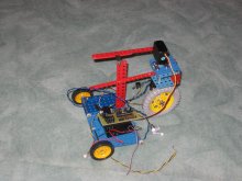 Fatima ver 2 |
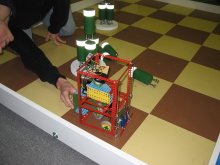 Ferda |
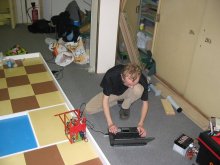 Jirka with Ferda |
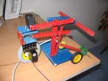 Ditch detection |
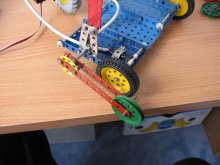 Ditch detection - detail |
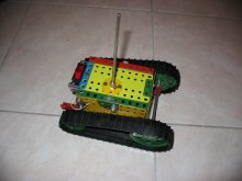 Final Fatima version |
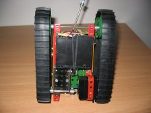 Fatima - bottom view |
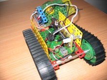 Fatima - inside |
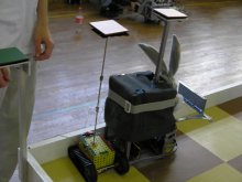 Ferda and Fatima at the start |
 Ferda in action |
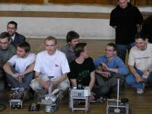 Robots at Eurobot |
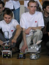 Short Circuits 2005 |
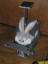 Ferda with mask |
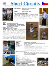 Jirka's poster |
We would be happy to answer any
questions you might have.
