Dana
21st place and Best Concept Prize, Eurobot 2003
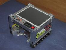
Dana is the result of our effort devoted to the Eurobot 2003 contest. We have hopefully learnt from the past mistakes (at least some of them). This robot tries hard to be both smarter and simplier at the same time than our past bots . The result is the 21st place and Best Concept Prize.
Quick Info
Dana is a successful successor of Barbora.
Thus you can find the same BLDC motors (each with 600W), motherboard with
AMD K6 500MHz, 128MB RAM and 128MB CompactFlash, video input, 100Mb Ethernet
and of course Linux. The navigation is based on odometry and infra sensors
CN70 detecting the color of the floor under the robot. Camera is used to
search for the pucks. The last sensor is a bumper to provide something as
a “last hope” of catching that the more advanced sensors and algos missed.
Update
The GPL'ed source code is now available for download (broken link).
Mechanics
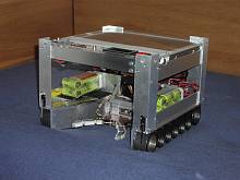
The robot is made of three main parts: boggie, hand and puck barrier for
the standing pucks.
Boggie
The most interesting part is the boggie, originally developed for
Barbora. The boggie is very sturdy, machined in a high quality from dural
(aluminum, copper, manganese and magnesium alloy). The threads give the boggie
very high stability and amazing acceleration and deceleration.
Already at that time we knew some of the disadvantages — first being
the odometry. However we anticipated the use of optical mice which —
in theory — should give us superior odometry taking into account
even skids (acctually any translation or rotation movement). The reality
was somewhat different. One reason was that our field was too shiny.
Another crucial point was the exact height of the mice above the surface.
Because of very high magnification the optical mouse has very short depth of
focus. This year we run without the mice, nevertheless we plan their
reincarnation. The result so far is very inaccurate odometry. There are
several causes for the errors. First of all we do not know the exact center
of rotation of the robot — there is no such thing on tracked vehicle
as a center of the line connecting the contact points of the wheels with
the floor. Typically is the center somewhere close to the center of gravity
of the robot but the exact location can shift due to the acceleration or
floor irregularities. Yet another important parameter is not well defined
either — R, the distance of the point of contact of a virtual
wheel with a floor and the center of rotation. Its determination is
complicated by the fact that the tracks have nonzero width (about 2.5cm)
and also that the point of contact with the floor has different distance
to the center of rotation in the middle of the track and at the end.
So it happens that the theoretical R is somewhere around 14cm
but the experimentaly obtained R is 19.5cm.
The value 19.5cm is the exact middle of the diagonal which means that
the robot rides most on the front and back wheels and that the small wheels
in between are just a pomp. The only thing that we know exactly is the
distance traveled because the tracks are made of synchronous toothed belts
that touch the floor with a straight surface. One revolution of the motor
therefore corresponds to 14.4mm when going straight and not skiding.
Another disadvantage has appeared over time — the track tend to make
the robot go straight. This effect is reinforced by the fact that Dana cannot
drive the motors with low RPM but with high torque — thanks to the
principle of operation of our motor controllers we can regulate only power
(PWM) and not RPM. Nor it is possible to slightly break one motor. Setting
one motor to 20% and the other to 4%, the robot still goes straight forward.
The last disadvantage is merely implementation flaw — the sides of the
belt pulleys have been cut off so that they do not surpass the belts (the robot
would then ride on the pulleys and not on the belts). But the cut off was
a bit severe and the consequences too. When one track is standing still and
the other under power the tracks fall off the pulleys. So far the solution
is in the software, forbidding the maneuvers causing the fall off.
The propulsive unit of the robot is made of two brushless DC motors.
Between the motors and the track there is two-stage gearbox made of HTD
synchronous belts. The ratio is 9:100 which is approximately 1:11. The encoders
in the motors give 18 pulses/rotation. The pulleys driving the tracks have 32
teeth, a tooth is 5mm. Considering all this gives us about 0.8mm/pulse.
The motors give 1480 RPM/V. The fully charged bateries give 14V (10 NiCD cells
per motor) which in turn corresponds to 5m/s (18km/h) — the speed of a
running man.
In reality that means that we do not use more than 20% of the available power.
Hand
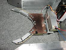
The hand is made of aluminum profiles and PCB board. It can go up/down, turn
and open/close. It grabs the pucks with three segment fingers. A servo with a
pulley and a string drive the fingers to open and close. The other two DOF are
also handled by servos. It should be mentioned that it can lift about 0.5kg
into the height of 6.5cm. The front part of the robot and the hand are shaped
in such a way that the even a puck laying 12cm of the axis of the robot was
picked up without course correction. You can se a prototype of the hand in action
in this video.
Puck Barrier
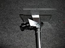
To throw off the standing pucks — that was the job of the plexiglass
puck barrier at the height of 11cm above the field. The tower of three pucks
passes bellow easily while a standing puck is knocked over. The robot however
cannot go too fast while hitting the puck because the puck can bounce of the
ground and "jump" on the hand the wrong way.
Driving the Motors and Other Outputs
Motor Controller
We use controllers TMM from MGM ComPro
fitted to accept commands through serial line. They are small, light, high-performace
efficient and probably the best thing you can have if you are making airplane
models. However if you are making robots…
The controllers are sensorless, meaning that they do not need any sensors attached
to the motor. Instead they determine the position of the rotor by sensing the back
EMF. When the motor turns slowly the generated back EMF is difficult to sense
and therefore the controller cannot drive the motors in low RPM.
The controllers should send a number of revolutions since last update.
A “tiny” problem is that this value is always positive (even when the motor
is running backward). Another "feature" is that the value should be zero
when the motor is not turning which is unfortunately not true. But thanks to
the manufaturer of the motors (Mega Motor company) we have older type of
the motors with built-in encoder that we use for odometry calculation.
Servo Control
The control the servos we use SOS-AT from Rotta.
It has worked fine thus far. However it could be easier to interface something
with I2C instead of serial line. This way we have to run more cables
to the hand.
Status LED
All inputs and outputs of the EzUSB microcontroller have controll LEDs connected.
This is a great feature for debugging. You can faster recognize that something
is not working properly. Further the outputs that are not connected to anything
can be used to signal different internal states of the EzUSB.
Brake Lights
There are six high luminosity LEDs connected using the PCF8574 to the I2C
bus. The LEDs can be controlled by software. We have six additional
debugging elements at our disposal. If not used for debugging they can
create some nice
KITT (Knight Industries Two Thousand)
effect .
Front Panel LEDs
On the front panel of the robot there are another two LEDs connected along
with 6 buttons through PCF8574.
Voltmeter
Another important part of the front panel is a digital voltmeter showing
the joint voltage for the electronics — not the battery voltage that
can be different on different packs (the robot can use up to 4 different batery
packs at the same time).
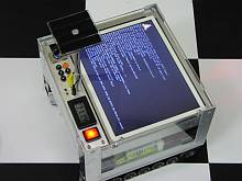
TFT panel
The top side of the robot is covered with an industrial high contras TFT
panel, 18-bit color depth, 800x600 pixel resolution.
Sensors
IRC (Incremental Rotating Counter)
Three opto gates inside the motor encode the rotor position. There are 6
posible states determining the absolute rotor position in one period of the
rotation of the magnetic flux. The motor has 6 poles meaning that we have three
periods per one mechanical rotation giving the total of 18 pulses per
mechanical rotation of the motor rotor.
We use the opto gates as regular incremental encoders in computer mouse
— only instead of 4 states 00 → 01 → 11 →
10 we have 6. That means that even when we miss one state change we can detect
the error and recover the correct pulse count.
Sensors for the Hand Position
There are no sensors dedicated to the detection of the hand position. Therefore
we have no means of feedback from the hand, we cannot detect if the hand functions
properly. Even the comunication between the SOS-AT module and the computer is
one-way so we do not even know if the hand is alive at all. The only feedback
we can use is the color detection for the puck or Sharp GP2 used to detect the
tower height.
Sensor for the Puck Presence and its Color
There are two infra CNY70 sensors to detect the color of the puck in the
hand (black/white). This way we can recognize if the puck should be turned, if
the puck is bonus (point for us no matter which way is up) or an evil one.
Another sensor on the hand is the opto gate to detect the puck presence in the
hand. Everything is connected using the PCF8591 to the I2C bus.
Sensors for the Field Color
The are another 7 CNY70 connected through another two PCF8591 to the
I2C bus. These are used to localize the robot using MCL
algorithm.
Accelerometers, Gyros, Compass
These advanced sensors were not integrated yet. The plan is to use 12-bit
A/D convertors MAX127 a MAX128 for the I2C bus to connect MEMS
accelerometers, iMEMS/Piezo gyros and permalloy compass. Using these sensors we
could calculate change in position which would then be used as an input in to
the MCL algorithm to calculate the current position. The advantage of the
approach is that the noise of the sensors does not depend on the outer
conditions of the robot (field surface etc.). Some work on this field is made
by the autopilot project which
is interested in building an autonomous helicopter.
Optical Mice
Last year there were 4 optical mice mounted on the robot. In theory they
should provide complete odometry including skids and slides. However noone
can guarantee the funtionality on the fields in La-Ferté. We still have them
and two of them are mounted on the robot for further testing.
Internal Camera
The robot has a cheap color PAL CMOS camera mounted on top. Using the
not-so-good image grabber on the motherboard we can use 352x288 YUV422 pictures
(16 bits per pixel). Sadly, when using 25 FPS the processor is running at 100%
(the grabber cannot do DMA). Therefore we have developed color thresholding
algorithm using only 5% of the pixels on average which seems to be working
fairly well.
External Camera
We are using 2.4GHZ wireless link to connect the external camera to the robot.
The camera is placed inside one of the beacons. The picture contains more noise
than that of the internal camera and sometimes the signal cuts off completely.
The advantage of this camera lies in its fixed position. The reciever is connected
to the same image grabber as the internal camera, which means that we cannot use
the cameras simultaneously. Switching the singnals from one camera to the other
takes about 2 frames (100ms).
Bumpers
In every corner of the robot there is a sturdy microswitch wired directly
to the EzUSB. The problem with the switches is that the robot must hit something
perpendicular to its front/back in order for the switches to detect it. We could
not make them bigger because of the spacial restriction made for the
Eurobot 2003.
Buttons
The front panel contains 6 buttons that can be used to control the robot
when the keyboard is missing.
Processors
PC
The computational power of the robot is composed of several processors.
The motherboard contains AMD K6-2/500, 128MB SDRAM, 128MB Flash disk, 4 UARTs,
parallel port, 2 USB ports, 4 video-in, stereo audio out and several audio ins.
The industrial motherboard further contains LVDS, PCI and PC-104 slot.
EzUSB
Microcontroller EzUSB runs on 24 MHz and contains several kB of memory.
It is connected using the USB bus to the PC. It also features 24 GPIO, I2C
master and 2 UARTs.
SOS-AT
The SOS-AT module is a board with AVR controller that controls up to 8 servos
(we use only three in the hand). It is connected to EzUSB using a serial line
running at 9600bps.
TMM
TMM are the motor controllers to drive the BLDC motors. TMM are made by
MGM ComPro. They are connected using UART
(19200) to the PC.
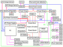
Overview of the Electrical Connections
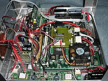
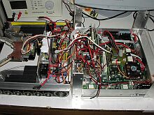
The estimate of the wire length inside the robot is somewhere around 15m.
The connector count must have reached hundreds. You can find the interconnections
on the picture as you can the bus types. Red is power, blue UARTs, green
I2C and purple the rest.
Software
EzUSB
EzUSB runs very simple program that continualy sends the state of all inputs
(I2C and GPIO) to the PC. It can also recive commands to set the
hand position using the SOS-AT, it can turn on/off the power to the hand and
the motors, read and set the periphery (CNY, buttons, LEDs) connected to the
I2C bus. Exept this it also counts the motor revolutions using the
built-in motor IRC. The polling frequenci is 3kHz which would not be possible
to do from the PC directly. Only the running sum is sent to the PC. The program
downloads through the USB from the PC.
Kernel of the Operating System
The main computer on the robot runs a custom fitted Linux. The hardware
abstraction is dealt with in the kernel (Daisy does
it through the serial line). The implementation on the kernel level allows us
to screen the user-level software from the details of the electrical layout and
buses (the motor controllers sit on the UARTS while the EzUSB on the USB). The
kernel sends the structure input_data to the aplication. The
structure describes the complete robot state. On the other side it accepts
the structure output_data that contains the commands for the hardware
— servo settings, motor PWM, LEDs settings…
Userspace
The userspace application is one single-threaded program that works in
cycle of receiving the sensor data from the robot, analyzing it and deciding
the next action and sending the appropriate commands to the hardware.
The software is divided into reusable parts that are in the lib/ directory
and standalone applications in the directories v0/, v1/, v2/ etc. We also have
some testing utilities such as dana-io-test to test the comunication
capabilities or cvtest to test the camera setup.
Libraries:
- gmcl
- GMCL
- iodrive
- basic functions for the userspace-kernel communication
- cvideo
- functions supporting the video grabber
- waypoint
- functions such as “go-to-place”, depending on the position suggests next action — turning, straight forward…
- fbgraph
- drawing through memory mapped framebuffer
- regions
- finding regions in pictures
Applications:
- v0
- straight forward until a puck is found, turn it the green side up and return to the starting position – video
- v1
- not finished – attempt to drive the robot according to the data about the square crossings, trying to to go parallel to the field sides
- v2
- drives around a rectangle using gmcl and waipoint
- joy
- (joydrive, joyride) control the robot using joystick
Algorithms
GMCL
GMCL (genetic Monte Carlo Localization) which actually has nothing to do
with genetic algorithms is used to track the current position of the robot
on the field. It uses input from motor encoders and from CNYs looking at
the color of the field under the robot.
GMCL works fairly well but the poor quality of the odometry sometimes
causes the robot to loose track of its position. One way to further improve
the algorithm is to create a better model of the motion of the robot (including
some of the dynamic properties). Another way is to change to path-generating
algorithm to include more "cik-cak" paths that give the MCL algorithm
more and better data (more corossings) to track the position. Yet another way
would be to incorporate inercial sensors such as accelerometers and gyros.
Driving (Waypoints)
The driving to a set place is implemented as a simple state machine with
hysteresis that decides if to go straight or turn in place. The hysteresis
makes the decision process more stable and reduces oscilations.
Image Processing – Finding of the Color Regions
A simple region finding is to threshold the image into color classes
and then use floodfill to connect them. For each compute the center of gravity
and weight.
We have designed a faster and relatively interesting algorithm that can
do all this fast (a single pass over the image). Further it is optimized to
use only about 5% of the pixel data of each image because retrieving the
whole image from the framegrabber memory is so slow.
Results
When the Eurobot international finale came Dana was not as finished as we would like her to be.
We knew there was still a lot of work needed on the software. What we didn't know was that the
little hand for puck manipulation is going to eventualy break down. Comparing to the rest of the
robot the hand was not sturdy enough. Despite of being completely hidden inside the robot it
suffered several collisions. The pucks would line up in the worst way forcing the hand out of its
range. Gradually its performace deteriorated so it was no longer able to manipulate the top most
puck of 3-puck tower and required frequent recalibration.
Despite the problems we managed to steal
some points from our opponents using the trick only Dana was able of — drive to the opponent's
3-puck tower, pick up the topmost puck, turn in upside down and place it back on the tower. One
single maneuver like this gave us +10 points advantage (opponent lost 5 points for its tower, we
gained 5 points for ours). All of this contributed to the
Best Concept Prize we were awarded. There is also an
article on Dana
at the French site.
Any questions can be directed to us through the
standard web form.
