Ball Manipulation
the quest for reliability and robustness
Ester's job is to collect small rugby balls at a 2x3m field. Last year's experience lead to the decision that reliability must be the main and most important property of any future manipulator. Dana's hand was nice and smart, but too delicate and Barbora's scroll feeder worked only sometimes and only with some balls. According to our observations the most reliable design for ball manipulation at Euroboot 2002 was the use of cylinders. Therefore cylinders are also the basis of our design.
 First design |
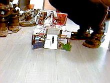
You can take a look at our first design at the picture. The mechanism
assumes that the balls are sufficiently compressable (and the motors in
the mechanism strong enough), so that it is possible to ignore the fact
that the balls are not spheres.
The mechanism works like this: the robot moves forward and
approaches the red ball. At this moment the brown cylinder is rotating
slowly, with constant velocity. The robot drives to the ball in a way
that the ball will be pushed between the cylinder and the floor first and
later then between the cylinder and the green metal sheet (the colors and
nomenclature taken from the schematic figure). Similar
to Barbora, but without the spiral. Then the brown cylinder is stopped
and the robot has to line up to the target. The ball is secured between
the cylinder and the green metal sheet and it is possible to drive through
the area. When it is lined up, the brown cylinder starts rotating again.
The ball is caught by the violet cylinder that rotates with a higher
velocity. That shoots the ball out. The violet cylinder's rotation
velocity determines the shape of the ballistic curve that the ball
follows.
You can see the first prototype made by
Pavel Jiroutek (Team Short Circuits Praha) on a video (you need the Xvid-codec
to play – download i.e. at http://koepi.roeder.goe.net/xvid.shtml).
Even prototype that simple worked astonishingly well. The cylinder only needs
a simple and small sprocket made out of Merkur (czech version of Meccano).
However it cannot shoot yet.
The prototype confirmed that a relatively strong motor is necessary to power
the main cylinder in order to overcome situations when the ball gets stuck
inside. The prototype uses a servo, modified for continuous rotation which,
alas, does not fulfill the requirements. Stronger motor is the so-called
brute-force appproach that usually works and is relatively easy to
implement but should be the last resort only when no “nicer”
solution can be found.
What alternatives are there to solve our problem? We will search for
an answer to this question until we better understand why this problem
arises and under what circumstances.
The ball can enter the shooting mechanism in an arbitrary orientation. As
long as it arrives “flatwise” everything is fine and it is transported further
without any problems. However when the ball enters oriented with the “tip
forwards” it could get stuck. The cylinder would try to rotate the ball further
into the direction where it is not round and than would not work out fine
.
There are to possible ways to deal with this:
- guarentee that the ball always arrives “flatwise”
- rotate the ball correctly inside, so that it cannot become stuck
The team Short Circuits Praha selected the first solution. Thanks to
the fact that the ball can be rolled in only one direction it is possible to
push the ball infront of the robot for a while. That lines up the ball in such a way
that it can freely roll into the direction of the robot movement. This is also
the optimal orientation for the ball to be sucked in by the cylinder.
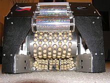
We chose the second solution, because we hope that the shooting mechanism
will be more reliable and robust and finally also faster. Basic building blocks
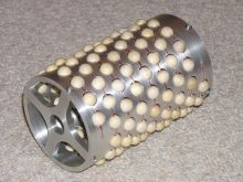
are wooden beads. The big brown
cylinder from our previous design is adapted so that beads are spread out
across the whole surface. That allows pushing the ball to the side without
friction. The “green metal sheet” is also replaced with a construction made of
the beads. Further the construction is shaped in a way that the middle section
is further from the cylinder and the edges are closer.
Holes for the beads drilled into the cylinder are on a spiral and the wooden
beads are threaded on a copper wire that is wound up on the cylinder.
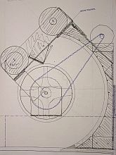
The whole construction can be seen on our drawing. The upper section
contains the shooting mechanism which consists of two independent
cylinders which provide the ball with the required energy. Their design is
based especially on the following data and computations:
A parabolic flight form is assumed, without air friction and the ball enters
the goal at the top of the curve (you can watch the mechanism on
a video).
|
|
Because the relation of ball and the cylinder energy is quadratic in relation
to the velocity with which the ball is let go, the energy ratio 1:10 stays fixed
even for higher velocities and it even gets better, because the
deformation energy is a constant. When brass is used, the energy ratio
is 1:30 (that is for shooting the ball into a distance of 2 m with an
angle of 10 degrees only 1/30 of the energy of the cylinder is
necessary).
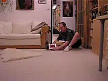
The shooting mechanism can be watched on the video while shooting
forwards and upwards.
We get back to you with more information as soon as we finish the mechanism.
16.7.2004
We are sorry but due to the work on the robot we somehow did not manage to
complete this article earlier. The good news is though, that the suggested
mechanism worked (nearly) flawlessly during the competition.
You can see how the finished mechanism looked like when mounted onto
Ester on the picture. The front part (in front of the camera that is used to
search for the balls) contains an infrared barrier to detect the incoming
balls. Other sensors include the encoders (without the
possibility to detect the direction of the rotation) on each of the three
cylinders. The sensory equipment could be mentioned as one of the biggest
shortcomings. During the time we designed the whole mechanism, it was
not really clear what kind of sensors would be needed and so we implemented
something simple thinking that should that prove to be insufficient we will
improve it. But as the competition date came closer and closer we
had many things of greater urgency. Apart from that, even now
it is unclear how the optimal solution would look like.
When we shot the ball to the goal right after colection, everything was
fine. Problems arose in the moment when we decided to collect several
balls and shoot them altogether. The algorithm for one ball looked like
this: (a) turn on the cylinder (b) when the infrared barrier is
interrupted count N encoder ticks and stop the cylinder (c) report
a ball in the robot. The modification for two balls was quite
complicated. The actual algorithm was more or less the same, but the
problem lied in the detecton of the number of balls in the robot.
When searching for one ball, it didn't matter how
many balls the robot actually collected (1, 2 or 3?), but when searching
for more balls this information was “somewhat” crucial.
Apart from that the strategy to search for several balls proved to be an
almost complete failure. During the first two fights in France we did not score
even once, because Ester kept on searching for a second ball after it had
already collected the first and typically ran into the opponent in the meantime
which caused the loss of position tracking and defacto the end of all chances.
We returned to our strategy “collect-and-shoot” but due to profound
modifications of the code to support collecting several balls, the detection was
not reliable.
On the other hand it was really nice to watch the actual shooting. The
shooting cylinders were crancked up to the appropriate speed for the given
distance to the goal and all balls in the robot were shoved through it
gradually. Aside from temporary drop-outs of the encoders due to
loose contacts, noone could really complain. Ester shot without
bigger problems even over the diagonal and always hit the goal.
If you have questions or remarks – contact us. We will happily answer
you. Thanks for most of the fotos, videos and computations to Vojtěch
Pavlík.
