Barbora
tracked vehicle with color camera and PC onboard, 2002
Barbora was designed primarily to participate in the Eurobot 2002 competition. Another even more important motivation to build the robot was the desire to build an universal bogie to be used in the following competitions and to have a reliable platform for further research and experiments. Unfortunately we have not finished the robot in time to qualify to the competition. However it has shown to be an excellent drive while building the robot and it has certainly helped us to achieve what we have.

Quick Facts
The robot is built around a PC-like motherboard
running a customised version of the Linux kernel. Two brushless DC motors
provide the power to move and 4 optical USB mice the required odometry feedback.
Additional sensors include onboard and offboard (wireless) CMOS cameras and
optical reflective infra red sensors to detect the color of the floor bellow the robot.
Unique helix storage system is the base for ball manipulation.
The software side includes
MCL (Monte Carlo Localization)
position tracking,
RRTs (Rapidly-Exploring Random Trees) path
planner and fast image analysis based on color tresholding.
Boggie

The boggie is built from the off-the-shelf components for the
most part, namely ones used for the aircraft and automobile models, as well as
some used in the process automation. The usage of the off-the-shelf components
was motivated by overall lower production costs of the robot, as well as by the
decrease of the developement time. Having done the preliminary design of the
boggie construction and functional parts, the manufacturing details were tuned
up by the company Vakuum Praha,
a company collaborating closely with the
Faculty of Mathematics and Physics,
Charles University in Prague where most of
the team members come from. Vakuum Praha specializes in vacuum science and and
precise machinery and has machined the boggie for us.

The boggie is made of aluminium to be light and durable. Viewed from above
the platform is roughly a squared, 30x30 centimeters (12 by 12 inches). The
height of the boggie containing motors and bateries is around 6 centimeters
(2.36 inches).

Locomotion of the robot is provided by two brushless DC motors
with neodymium cores produced by a Czech company
Mega Motor. These motors are
lightweight (160 grams, 0.4 pounds) and provide excellent mechanic power —
more than 600W each, giving the robot 1.2 kWatt (1.6 horsepower)
peak thrust,
resulting in peak acceleration of 20ms-2 (2G). The maximum speed of the
boggie is 4ms-1 (9 mph). The robot should be able to reach the maximum
speed in less than a quarter of a second (expecting perfect adhesion, no
sliping). To achieve good stability (even in high speeds and obscure manoeuvres)
and high traction the boggie is equipped with tracks made from industry standard
HTD synchronous belt. Similar belts are used for a gearbox between the motors
and the tracks because we have not been able find a more suitable gearbox
fulfilling such a high requirements such as the ability to handle the power and
high rpms and size small enough to fit inside the boggie.

The drawback of the motors is that they require a quite complex electronics
to drive. Since they have no mechanical commutator they require three phase
power with variable frequency at low voltage (12 Volt) and high current (50
Amperes peak). On the other hand due to the the lack of mechanical commutator
the motors offer unprecedented reliability and very high power/weight and
power/size ratios.
Fortunately the
TMM 40e-3ph motor
controller produced by a Czech company MGM-Compro
is exactly what we needed and with some necessary modifications to
its software (kindly made on our request by the manufacturer) are easy to use
with our main computer. The modifications consisted mainly from adding the
serial line communication instead of the regular PWM control signal used for
radio controlled models.

As a power source 20 NiCd cells are used, with aggregate voltage of 12V, and
capacity of 3400mAh. This allows the robot to run for 2 minutes (a match in the
Eurobot 2002 competition lasts 90 seconds)
at maximum power consumption. Because
the real power consumption is approximately ten times less, this is more than
enough (for the competition). However the test runs usually lasted much longer
and the drawback of the construction was that the bateries had to be recharged
while mounted on the robot. That forbided simultaneous testing and recharging
which in turn has made the testing unconfortable and less effective. For further
usage the batteries has to be made replacable to remove this limitation.
Ball Manipulation


A double copper helix is the base of the ball manipulation system. The helix can
store up to 7 balls inside the body of the robot. This allows the robot to
collect as many balls as possible and to distribute them in to the appropriate
baskets later on. The system is mounted on the top of the boggie in order to be
easily replaceable by other manipulation devices for future competitions and/or
research.
The balls are first collected by the opened part of the U shaped boggie. When in
the front part the ball is lifted by a pair of little manipulation arms. These
arms are powered by regular servo motors and driven by custom board based on the 555
chip. The board is connected to the LPT port of the mainboard.
The arms were the single most troublesome part of our robot. We expected them
to be an easy fix and that's why we have postponed theirs fabrication having more
important things to build. However it has proved to be a real headache, not working
all the time.


When lifted 8 cm above the floor the ball is taken by the helix storage
system. The helix itself stays fixed and the movement of the balls up or down
is achieved using a rotating cylinder in the center of the helix. The cylinder
is made of an aluminum pipe with a DC motor and two planet gearboxes inside.
The cylinder is fastened to the boggie with a smaller pipe coming out of it in
the center. The stator of the motor inside is attached to this pipe. The output
of the double gearbox (and in turn the rotor of the motor) is attached to the
outer housing made of the larger pipe. The overall effect is a cylinder with two
wires coming out of it with a rotating outer housing when power is applied to
the wires.
Electronics

The main controll unit of the robot is a single board computer
manufactured by Advantech,
PCM-5864,
20×12 cm (8×5 in), equipped
with an AMD
K6®-2 processor running at 500 MHz, 128 MB of RAM, audio
and video inputs, a 100MBit ethernet connection and an USB bus.

The motor controllers return the distance traveled. This information can be in
principle used to calculate odometry. However, treaded vehicles suffer from the
fact that the very principle of their operation is skidding and sliding offering
very poor odometry data. To supplement the information about relative movement four USB
IntelliMouse Explorer optical mice were used, offering resolution of
400 dpi and maximum tracking speed of 1.5 ms-1, by scanning the underlying
surface at a refresh rate of 6000 frames per second. As optical sensors don't
skid or slide over the surface, the robot can do manoeuvres (ie. controlled
skiding and sliding) which classic odometry navigation using IRC (Incremental
Rotating Counter) is not able to cope with gracefully.

The mouse based sensors provide relative movement information only. Therefore,
the error of the estimated position on the playfield can grow out of bounds with
time. To avoid this, the robot has five Vishay
CNY-70
optical reflective infra red sensors to
detect the color of the floor underneath itself. In the competition the sensors
were used to detect a line grid drawn on the table. Using this data, the
cumulative effect of the relative position tracking can be eliminated using the MCL
(Monte Carlo Localization) scheme.

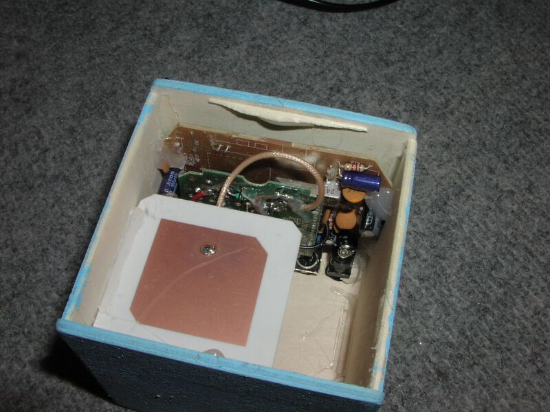
The power to the electronics is delivered by a switching power supply based on
Maxim MAX787 components. This gives the
computer relatively stable input
voltage, while the voltage of the batteries varies under the load.
In order to locate the balls on the playing field the robot is equipped with color
CMOS camera. The camera is connected to the main computer through a CVBS interface.
Since the main board has video input, the picture from the camera is immediately
available for processing. In addition to the onboard camera the robot can
receive TV signal through microwave connection from an offboard camera located
in the corner of the plaing filed (in a beacon).


Software Architecture
Since we use industrial PC we are able to use the Linux operating system.
Linux gives us us maximum freedom in customizing the kernel and drivers for
maximum performance of the robot. The robot control software is partially
implemented in kernel (realtime critical parts) and as userspace processes
(CPU intensive computation — image processing, navigation, path planning).
Kernel Drivers
Going with the description in a bottom up manner we start with the kernel
drivers. The kernel drivers are composed of modules: tmm.o, mailbox.o,
fifo.o, mice.o, ct69k.o, cvideo.o, serio.o, serport.o, elevator.o. Modules
mailbox.o and fifo.o implement our own interprocess communication primitives.
Both require special inode to be created and from the user perspective act like
a file, meaning that it can be opened and closed, data can be read from it or
written to it and process can wait for a data to arrive. What differentiates our
IPC from the ones already provided by the kernel is the transparent support of
one-to-many and many-to-many communications.
Mailbox is a storage for a single data structure. Typically one process
writes the structure and other n can read it. Once a process reads the
contents of a mailbox the mailbox appears to that process empty (ie. a process
cannot read the same value more than once). If the mailbox is opened as
blocking, next read will stop the reading process until new version of the data
is available (ie. until the producing process writes into the mailbox again).
Fifo implements a queue-like access. When opened for reading it is
initially empty. When opened for writing and no process has opened it for
reading yet, it acts like a black hole throwing away all data written to it. When
a process opens the fifo for reading it starts receiving all the data written
to the fifo after the opening.
Other kernel modules are responsible for the various hardware parts of the
robot. The userspace programms can communicate with the hardware through
mailboxes, fifos and special devices created by these modules.
The hardware includes the TMM 40e-3ph motor controllers (tmm.o),
the IntelliMouse Explorer optical mice (mice.o), the video input (ct69k.o, cvideo.o)
and the helix storage device (elevator.o) connected to parallel port.
Localization (position tracking)
A position information is calculated using the
MCL (Monte Carlo Localization) algorithm. Relative movement
information is obtained from the optical mice. Each pair of mice provides
information about the change in position and orientation. We have 4 mice because
the mice has proved to be very unreliable in our context. The mouse requires
precise alignment with the surface and very precise height above the surface
(this height is also quite small). Because the optical sensor uses magnifying
lenses to detect even small irregularities on the underlaying surface it has
short focus range. If the mouse is too high or too low it reports invalid data.
Also the white lines present on the Eurobot 2002 playing field gave the mice
real headache. Using 4 mice instead of the minimum 2 gave us the advantage of
receiving 6 times (each pair) supposedly the same information allowing us to
filter out some of the problems.
The information about the relative displacement and the change in
orientation was used in the MCL algorithm. The MCL approach applies
sample-based representation of the three-dimensional state space of the robot.
When the robot moves or senses, sampling / importance re-sampling is applied to
propagate the belief over time integrating relative displacement information
with other sensors supplying information that can be compared with a known map
thus reducing the otherwise unbound growth of the integration error.
Path Planning
Our path planning algorithm is an implementation of
RRTs (Rapidly-Exploring Random Trees). A
Rapidly-exploring Random Tree is a data structure and algorithm that is designed
to efficiently search in nonconvex high-dimensional spaces. RRTs are
constructed incrementally in a way that quickly reduces the expected distance of
a randomly-chosen point to the tree. RRTs are particularly suited for path
planning problems that involve obstacles and differential constraints
(nonholonomic or kinodynamic). RRTs can be considered as a technique for
generating open-loop trajectories for nonlinear systems with state constraints.
An RRT can be intuitively considered as a Monte-Carlo version of a Voronoi
diagram, and certain variations can also be considered as stochastic
fractals.
The path planning takes commands from the strategy module and outputs a path.
In addition it uses the information about the current location of the robot and
the current locations of the balls. Output of the planning algorithm is a path
specified as a sequence of waypoints. Each waypoint contains displacement
relative to the previous waypoint in the sequence, the expected translational and
rotational speed and the time when to reach it.
Driving
Input of the driving module (the so-called wheelman) is the path
generated by the path planner. The wheelman's role is then reduced to a linear
interpolation of the current translational and rotational speed from one
waypoint to the other. The speeds are set by a feedback control loop based on
the PID algorithm. The required feedback is supplied by filtering the data from
the 6 pairs of mice.
Image Processing
The heart of our image processing module is YUV threshold based classification.
The camera geometry is calibrated and the positions of the balls relative to the robot
are calculated based on the fixed position of the camera with respect to the
robot and the pixel coordinates of the respective color cluster.
Object Tracking
The purpose of the object tracking module is to filter the output of the image
processing module using some information about past positions of the reported
balls. A Monte Carlo algorithm similar to the one used for the localization has
been used for the object tracking. Since all the balls of the same color are
from the point of image processing indistinguishable a single distribution is
used for equally colored balls. However this algorithm was computationally
expensive and it's performace was not as good as expected. The conducted
experiments suggested that regular averaging over last couple of frames is less
computationally expensive and more reliable. According to the results a decision
has been made to abandon the Monte Carlo tracking in favor of the simple
averaging.
Strategy
The strategy planning module is based on the assumption that the robot is able to
perform certain elementary actions. The task of this module is to generate a sequence
of these actions in order to maximize the chance of winning a match in the Eurobot 2002
competition.
Our first approach was based on hand-coded winning strategy using a FSM
(finite state machine). The approach had two primary flaws as we have
discovered later on during the developement:
- the offline design of the optimal strategy (ie. before the match) appeared harder and harder during the developement to that extent that we all agreed that it is nearly impossible
- even if it was possible the robot would never have enough information (ie. complete) about the state of the match to act according to it
The second approach is based on discretization of the game state space.
For each state there is an evaluation function which returns the worst possible
score that could be reached. This score is based on the assumption that the robot
can choose a “best” basket and decides to “defend” it — stand in front of it
not allowing the oponent to take balls out of it and expecting that the oponent is
as good as possible and has collected all the other balls.
The worst score is used to determine if the execution of a selected action
can lead to a worse final score or if even after the execution of the action
it is possible to maintain the current worst score. The safety of the execution
is calculated for some constant time interval into the future.
The selection of the next action is based on two assumptions: the action is safe and
the action is a part of a sequence that leads to an improvement in current worst
score.
The elementary actions the robot was able to perform were to move to a point
[x,y,α] or to command some of the actuators onboard. The elementary
actions could be hand-combined to form compound actions. The planner then
can build the plan using the compound actions. For example to take a ball out of
the basket is a quite long sequence of movement and actuator commands that can
be reused many times. By using the compound actions to build the plan the plan
stays compact and relatively short (less branching). The fact that the compound
actions can be decomposed to the elementary actions allows uniform determination
of the level of the safety of the plan and also the executive responsible
for executing them works with a well defined interface.
Conclusion and Further Work
A mobile robotic plaform Barbora was introduced. The
platform is ready for deployment in our research facility.
Unfortunatelly the hardware proved to be more complicated than any of us
expected, leaving virtually no time to debug and tune the software in time to
compete at the Eurobot 2002 competition. However the competition has proved to
be an exceptional motivation while building the robot. Further work aticipates
polishing the software level and providing more experimental results about its
performace.
People
| Vojtěch Pavlík | mechanics, electronics, navigation, Linux kernel |
| Kamil Řezáč | mechanics, electronics, motor control |
| Zbyněk Winkler | strategy, high-level control |
| Martin Mareš | image processing, strategy, Linux kernel |
| Petr Daněček | image processing, object recognition |
| Jan Kára | path planning, RRT |
| Jaroslav Sládek | object tracking, finances |
| Markéta Kyloušková | French interpreter, moral support, T-shirts |
Funding
This project could not be realized without the funding and support of following people and organizations:
- Smrcek, American University of Guttenberg
- Faculty of Mathematics and Physics, Charles University in Prague
- Physics on Stage
- MGM Compro
- Loctite
- and all the team members that filled whatever there was missing
If you have found this project interesting or you have some comments
about it, please feel free to use our
feedback form.