Ardusimple simpleRTK3B
Millimeter level GPS/GNSS receivers
SimpleRTK3b boards by Ardusimple provide millimeter level GPS/GNSS localization. In a pair, one can easily work as an RTK base station for the other. But not only that, SimpleRTK3b Heading has two antennas and can report its, as the name suggests, heading! Let's figure out how well it works. Blog update: 28/9/2022 — Time to go
Blog
September 12th, 2022 - What are these boards and what makes them interesting?
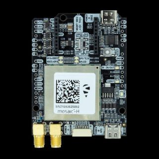
Ardusimple simpleRTK3B receivers are triple band high precision GNSS RTK boards based on Septentrio Mosaic-T and Septentrio Mosaic-H modules. They promise millimeter-level accuracy. Two Ardusimple boards can easily provide, resp. consume, RTK corrections over different radio channels, such as XBee, Bluetooth, Wifi, 4G/3G/2G or Ethernet. They can also receive PPP-RTK corrections from satellites (paid service).
SimpleRTK3B Pro, using Mosaic-T, is an Ardusimple GNSS solution that is to be used either as an RTK base station, or for "normal" localization in a rover, i.e. moving, mode. With a triple band antenna, it receives signals from GPS (L1C/A, L1PY, L2C, L2P, L5), GLONASS (L1CA, L2CA, L2P, L3 CDMA), Beidou (B1I, B1C, B2a, B2I, B3), Galileo (E1, E5a, E5b, E5 AltBoc), QZSS (L1C/A, L2C, L5) and NavIC (L5).
SimpleRTK3B Heading is what caught my attention. Although it supports fewer technologies (GPS: L1, L2, GLONASS: L1, L2, BeiDou: B1, B2, Galileo: E1, E5b, QZSS: L1, L2, NavIC: L5), it has two antennas and uses them to report not only location, but also heading.
For robotic applications, such as autonomous transportation in Robotour, it is vital for a robot to not only know where it is, but also where it is going. Most current robots rely on a combination of a magnetic compass with IMUs (gyroscopes, accelerometers), optical odometry and/or with GPS/GNSS. IMUs and optical odometry cannot provide heading relative to an absolute reference and GPS/GNSS only provides a point estimate and direction needs to be estimated from measurements distant both in space and time, which makes magnetic compasses critical at least for initialization of the heading estimate, but typically also while the robot is moving to correct accumulated errors in the estimate. However, in a typical city environment, a magnetic compass gets easily disturbed. For example, during Robotour in Deggendorf many teams observed compasses pointing in wrong direction all the way along a train track. In other Robotours, we were also able to detect underground power cables to street lamps this way. Altogether, magnetic compasses are an unreliable source of information.
In the past, I have also tried putting two SimpleRTK2B boards on a robot and, optionally, a third one on the ground. The stationary one on the ground served as a static RTK base station, one on the robot as a moving RTK base station corrected from the static base station (optionally), the second one on the robot used in the RTK rover mode and corrected from the moving base "station" on the robot (strictly necessary). The idea was that relative position between the "rover" board and the "moving base station" board on the robot gives heading. Alas, it did not work. The rover board did not, most of the time, achieve a full RTK fix and the relative position between the two boards on the robot, resp. their antennas, was too noisy to be useful. The leading hypothesis is high level of RF interference all around the robot. In our experience, this is mostly coming from USB3 cameras such as RealSense, Luxonis/DepthAI or MyntEYE. Alternatively, it is also possible I was not passing RTK corrections between the two boards on the robot fast enough. I could not use the radio link, because it was reserved to receive corrections from the stationary base station.
So, does putting two antennas onto a single board, like SimpleRTK3B Heading, solve the problem? Let's see next time!
September 15th, 2022 - Hardware and software setup
Before I go into measurements, let me share what hardware I am using and what software I use to interact with it.
I have equipped SimpleRTK3B Heading with two helical tripleband antennas. They are easy to mount on a robot without taking much space. SimpleRTK3B Pro as a base station has much more space and therefore I got a survey antenna for it. Save yourself some troubles and do not buy the antenna cables from Ardusimple. Mine fell apart immediately after it arrived. Other cables work fine.
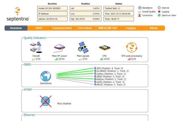
On the software side, I was very worried about my ability to configure the boards from Linux. Instructions say that after connecting the device to my computer, an external drive will show up and I can install drivers for Windows from there. Not very useful for my case. After I install them, I will get a web interface, they say. But what about without them? The good news is that Septentrio, the producer of the GNSS modules used on the Ardusimple boards, provides RxTools also for Linux. Even better news is that it works on my system (Debian Testing). The bests news of them all is that even without installing anything, a virtual network card (usb0) shows up with a pre-set IP address and the web configuration interface on http://192.168.3.1/ becomes available.
I use XBee Long Range to pass RTK corrections from the base station to the rover. It comes preconfigured from Ardusimple to Just Work. Nevertheless, you may want to reconfigure it or at least change the network id to reduce interactions with other teams during a robotic competitions. For that, you need XCTU by Digi. It also comes with a binary installer for different systems.
SimpleRTK3B Heading provides the heading information in an NMEA HDT sentence. Your processing software needs to understand it. If you want even more, such as tilt or position relative to the RTK base station, you need to parse proprietary NMEA messages described in the Reference Guide (sign-up needed). You may need to write the parsing software yourself.
Hardware is ready, everything is set up, does it work? I cannot wait to see the results!
September 18th, 2022 - Measuring direction, without RTK
It is time to measure the heading! Let me start with an important note: I did not use RTK corrections for this to make the situation more difficult. Nevertheless, there was a reasonably good view of the sky.
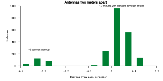
First, a measurement with antennas two meters away from each other shows that the SimpleRTK3B Heading board has an initial warmup period, which is noticeable across multiple measurements, and that after the warmup, the measurement is very stable. It fluctuates with standard deviation of 0.04 degrees, which I find amazing.
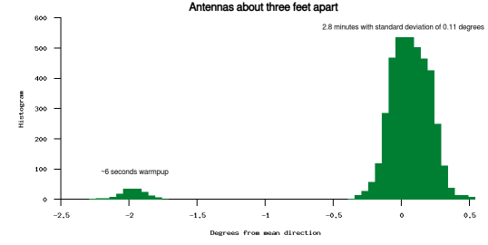
When I place the antennas closer to each other, about 1 meter apart, which is the minimum distance recommended by Septentrio, I see fluctuations in the heading estimate with standard deviation of 0.11 degrees.
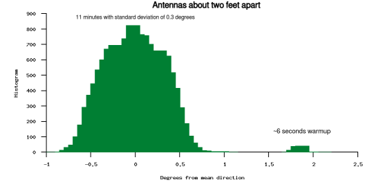
On my robot, it is more convenient to place the antennas even closer to each other. So what if I put them two feet apart? Standard deviation of 0.3 degrees. It is getting worse, but I still like it.
With the length of my shoe as a secret ingredient into a rough estimate, I am getting relative placement of the two antennas within two millimeters precision (standard deviation), i.e. four millimeters for two sigmas (95 % of the data). Millimeter level GPS/GNSS indeed.
All this while the position estimate itself is floating around. During the measurement with antennas two meters apart, the position estimate for the main antenna was moving back and forth by several meters in all directions.
This leads me to believe that the board locates, very precisely, the heading antenna relative to the main antenna and it does not really need an accurate estimate of the position of the main antenna. Therefore I do not expect that enabling RTK would change the results.
September 20th, 2022 - Round and round
Martin asked, if the GPS/GNSS, with RTK, is reliable enough to have the robot going back and forth on the same path for very long. That sounds boring. Eww! But what about a carousel? Let's go round and round!
In the video below, you can see how I initially struggled with the task, figured out the weak point* (hint: not the GPS/GNSS), fixed it and nailed it.
- Hey kids, do you know why logging everything is important? This is why. I can DEBUG ISSUES. OMG, A SUPERPOWER!!!
Anyway, let's go to the video …
In case you are wondering if this could work without RTK: Not with this stateless control algorithm at this diameter of the circle. With the fluctuations of the position estimate by two meters within minutes that I showed previously, the robot does not know at which side of the circle it is. I can imagine it would work after fusing GPS/GNSS with odometry and/or IMU, but that would not be saying much about the GPS/GNSS boards, would it?
September 25th, 2022 - Not going anywhere
There is one more basic measurement that I should have done in the very beginning. How stable is the GPS/GNSS position estimate when using RTK base station?
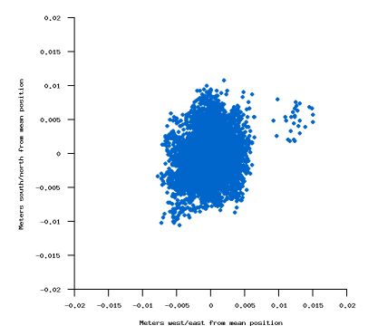
When I keep the SimpleRTK3B Heading board stationary, use SimpleRTK3B Pro as the RTK base station and ignore the first ten or so warm up seconds, I see 4 millimeters of standard deviation. I.e. 95 % of measurements should be within 8 millimeters of the mean value.
In case you like the results so far, there are also lower budget alternatives to SimpleRTK3B Heading, such as part 1 plus part 2. You may need one more module like that as a base station and you will likely be on your own with passing the RTK corrections from base to rover. I haven't tried these, but ZED-F9 comes from U-blox, a Swiss company, and we all know that what comes from Switzerland is perfect, don't we?
In case the results so far are not good enough for you and you are willing to invest more, solutions like Vectornav VN-300 combine dual antenna GNSS with accelerometers and gyroscopes in one calibrated package. Vectornav's estimate of GNSS heading precision matches mine with SimpleRTK3B Heading and I expect Vectornav's IMU part of the package to stabilize position estimates when there are no RTK corrections.
September 28th, 2022 - Time to go
Before I dive into more data from the robot, I would like to share few practical considerations. First, the screw holes on the board are weirdly placed and, as far as I know, CAD drawings of the boards are not available. Have fun making a case for it. Second, if the board does not work on your robot, turn the USB3 camera, most likely the depth camera, off. If this helps, you need to move the GPS/GNSS antennas as far as possible from everything related to USB3 and/or put a metal plate under the antennas. This is a known issue. You may benefit from new USB cables.
Now to the new data: I took the robot for a drive on a street I know is difficult for GPS/GNSS. There is a high concrete wall on one side, with a building just above it and there is a tall building on the other side. The visibility of sky is limited. I did not enable RTK corrections, because I was in a mood for pushing the limits again.
In the picture below, look at the light blue line. This is a position estimate from SimpleRTK3B Heading on a robot moving pretty much straight, within the limits of what manual control by joystick and the street allow. Reminder, without RTK. What you can see is that at some point the estimate started drifting sideways. What you cannot see is that the heading estimate continued pointing in the correct direction. This is physically impossible for the robot. At least until we get ice on the road. This is actually good news! It means it should be possible to use the heading estimate to correct the estimate of the position! While at it, I fused the GPS/GNSS position and heading with odometry. You can see the combined result as a red line in the picture.
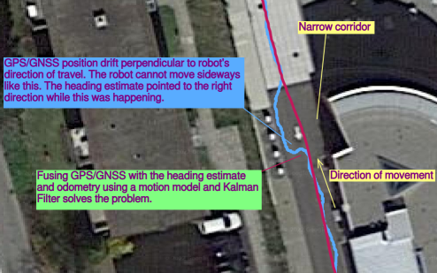 Sideways drift of GPS/GNSS position corrected by fusing position, heading and odometry with a Kalman Filter |
You could argue that I should be able to get a straight line like this from the odometry alone. Yes I should. But that's not the whole story. The white part of the street at the top of the picture is a traffic-slowing surface relief. It shakes the robot heavily. Enough to temporarily lose full contact to the ground when I drive the robot fast enough, which I did. Altogether, the odometry alone, after finishing a 440 meters long loop, ends up reporting a position 124 meters away from the starting position. The fused localization reports position just below two meters from the starting position. Some of it being because of me not finishing on exactly the same spot, even though I tried.
While I still see room for improvement of the localization in case of unavailable RTK, it will mostly come from other sources, such as IMU or visual odometry, and not from the GPS/GNSS. So with that, I am going to conclude the series: The heading estimate works very well, even when the position itself is unstable. Without RTK corrections, I find the position estimate to be OK, but not impressive. The robot cannot stay on the road just using that alone. With RTK, in the neighborhood of the base station and with unobstructed view of the sky, the robot can achieve subcentimeter "robotic" precision. The Ardusimple boards are easy to use and are configurable even on Linux.
