AppleBot
robot for harvesting apples
Two weeks ago a UK company contacted CZU regarding Robotic arm for apple harvesting. The motivation is that to find cheap work labor for picking apples is getting harder and harder, so the company would like to buy or develop a technology capable of autonomous apple picking. In this article you can find our development blog. Blog update: 30/1 — The Others (part1)
Content
- Apple 3D scan
- Back to 2D
- cv2.MSER
- Three apples?!
- Probabilistic Sphere
- URCaps
- PoE IP Camera
- Dual Sensor
- 2nd 3D-Scanning Experiment
- applethreshold.py
- Crazy Ideas
- Memories and UR5 API
- Apple Generators
- Recording H264 video
- stereo_match.py
- matplotlib
- The First Tests with Universal Robot UR5
- UR5 Video
- Applebot UR5 ver0
- The Hand
- Standa and UR5
- The Others (part1)
Source code
Blog
3rd December 2014 — Apple 3D scan
Yesterday we did the first experiment with apple recognition at CZU. We used
already existing tools:
- TiM55x laser scanner
- effector for linear motion (developed for some soil analysis)
- laser.py from Eduro project
The sensor TiM55x we obtained thanks to
SICK Robot Day 2014 participation, but we
never throughly test it. It should be similar to older versions, but … there
were two details:
- the IP was just crazy: 169.254.225.156 (we had to use old notebook with SICK software to find this out. Once this was set correctly sensor responded also to ping commands)
- if you send authorization command, used for LMS100, you got only old scan
The simple
scanning script
just collects data as fast as possible (over Ethernet) and stores them in
date-time-filename generated log file(s).
The experiment was a with growing citrus tree with attached apples like for
Christmas . And the results?
First of all TiM 55x has coarse resolution than former (and bigger) LMS 100
— 1 degree instead of 0.5 degree. 350 readings corresponded to 0.777m and it
took 32.28 seconds. I.e. approximately 10Hz and 0.024m/s motion. So in X
we have resolution 2.4mm and Y depends on apple size and distance from the
scanner.
Would you like to see the results? I would recommend to download
CloudCompare for 3D point clouds
visualisation. It is necessary to convert laser scanner data into point cloud
and you can use
log2pts.py
script. Here is also at least one example scan_141202_183934.zip. Note,
that you have to unzip it first.
And here are the first views in Cloud Compare:


Small disappointment? Well, I have to admit, that I have not recognize it too
at first sight. It is necessary to rotate it a little, you should easily
recognize the railing and the three walls are ground, wall and the ceiling.
People probably still prefer camera images, right .

4th December 2014 — Back to 2D
Today I will start with a reference to an article: Juan Feng, Gang Liu,
Shengwei Wang, Lihua Zeng, Wen Ren, A Novel 3D Laser Vision System for
Robotic Apple Harvesting, 2012 ASABE Annual International Meeting
(direct
link). They did something very similar to what I wanted to try — 3D laser
scan of the tree and then search for the apples.
First of all here is the
log2pgm.py
utility so you can see scanned distance data as 2D image. If you run
it on the data I posted yesterday you will get:
 distance image with two apples |
So it is maybe better to view 3D data as 2D image — it is in reality
projection of the 3D world on a cylinder, so we have all necessary info there.
Note, that I used fixed scaling of distances to grayscale. This way I will
not loose distance information (when compared to the referenced article). I
expect that scanned tree is not further away than 1 meter (otherwise it would
require slightly different scale).
Do you see the two apples on the citrus tree? I do . The darker one is
closer so it is larger. The image is flipped in Y-coordinate, as we scanned
this particular one from right to the left, but it is just a detail for the
moment.
So what next? Basically the same as we planned to do in 3D: we expect that the
apple has some size limits. These corresponds to some bounding box in 3D. In
grayscale image this means thresholding with narrow window and then searching
for objects of given size.
There is another rule we can also add: the apple should not have holes, i.e.
occluded parts have to be closer/darker otherwise detected object will be
rejected.
5th December 2014 — cv2.MSER
I wanted to get Version0 running this morning, but I was a bit naive. At
least I prepared necessary tools for 3D image analysis.
The first idea was to use threshold with lower and upper limits. You can play
with the threshold yourself: all you need is output from
log2pgm.py and
cv2-bits/threshold.py.
You can track both apples with minimum distance in the center and complete
shape in 10 steps corresponding to 5cm.
Then I was thinking that even cv2.MSER will extract easier what we need
(see code
diff).
MSER worked fine in AirRace rectangle
detection, so maybe apple object are also well separable? Some are and some
are not, see the temporary output:
 output of MSER with restricted BBox size |
You can see that darker left apple was not classified as candidate. It is
clearly the nearby branches spreading the blob. On the other hand even the
ligher (further away) apple was not obvious. I did not measure them, my fault,
so I expected size like 10cm and this seems to be 6cm?? Here is the console
input/output if you would like to repeat my steps:
m:\git\applebot>finder.py 0.06 logs\scan_141202_183934.txt
(380, 274) uint8
0.0696 (15, 138) (44, 149)
0.0528 (0, 132) (22, 141)
0.0504 (125, 138) (146, 148)
0.0648 (124, 137) (151, 153)
0.0672 (123, 137) (151, 156)
0.0648 (208, 116) (235, 139)
0.06 (171, 136) (196, 146)
0.0576 (75, 149) (99, 159)
None
I should also correct my statement about count of „apple points” as a
function of distance to scanning device. In X coordinate the size (bounding
box in pixels) should be the same. It is necessary to take into account that
due to shaking the readings corresponding of nearby object will be much more
reliable, but still, the size will be plus minus the same.
The difference is in Y coordinate is on the other hand significant. The
resolution if given by scanner resolution (1 degree), so an apple in 50cm
distance will have double the number of points when compared to an apple in 1
meter.
What next? I is necessary to filter out obviously wrong detection rectangles:
- find median distance value
- verify aspect ratio of detected rectangle (closer apple should be thin while further thick)
- verify compactness of the surface (no holes)
I would guess that these simple steps will already give the apple but let's
wait for real verification.
And what after that? Well, now we have the whole 3D scan in powerful
NumPy array so once we have
potential object we can return back to high resolution (laser readings are in
millimeters) and play for example with surface normals. I would be quite
curious if you can really reliably extract them and then try 3D object matching
like in Model
Globally, Match Locally: Efficient and Robust 3D Object Recognition paper.
6th December 2014 — Three apples?!
I must admit that the experiment last Tuesday was a bit spontaneous and now I
have the impression that the very last 3D scan (the one I
uploaded data) is actually with 3 apples! That some
joker placed extra apple on the box (the next time we will automatically
record it with Eduro IP camera to have reference pictures with timestamps):
 candidates detected by MSER |
In mean time I received dimensions of scanned apples:
- smaller one is 7cm in diameter and 5.5cm high
- yellow apple is 7.5cm in diameter and 7cm high
I should also mention a
bugfix
of numpy array conversion. I am learning it and I must admit it is very
powerful library. The bug was in my conversion from int32 to uint8 and that
was the source of horizontal lines. The corrected code looks like this:
tmp = np.array( scans ) / 5
mask = tmp > 255
tmp[mask] = 255
So you can define Boolean mask and then modify all elements where the mask is
True with single operation (see hint source at
stackoverflow.com).
Here
is code used for above picture. The parameters for MSER are slightly modified
(threshold step 8 instead of 1) and there is a new function isItApple() for
verification of the patch (in this context a submatrix of original 3D
scan/array). Also inside (half the size in X and Y so 1/4th in area)
elements are dumped:
m:\git\applebot>finder.py 0.065 logs\scan_141202_183934.txt
(380, 274) uint8
0.0672 (123, 137) (151, 156)
205
[ [102 102 103 255 101 101 102 255 255  50  79 107 103 101]
 [126 126 125 126 125 125 126 125 125 101 117 125 125 111]
 [123 125 125 125 125 125 117 111 123 124 122 125 124 125]
 [ 83 115 124 124 121 109  99  98 110 123 124 124 124 124]
 [ 66  73 122 124 104  98  99  97 111 124 123 123 124 124]
 [ 64  65 117 115  97  98  98  95 119 122 123 123 124 124]
 [ 65  64  96  97  96 100  94  97 121 121 122 121 122 123]
 [ 64  65  87  91  96  98  92 112 121 121 122 121 122 122]
 [ 65  69  91  91  94  95  96 111 115 114 114 115 114 115]
 [ 69  79  88  90  89  89  92  99 100  99 100  99 100 101] ]
0.0672 (88, 165) (116, 179)
94
[ [111 108  58  24  21  21  21  21  22  20  21  22  22  22]
 [ 17  19  20  21  21  20  21  21  21  21  21  22  22  22]
 [ 19  20  20  21  21  22  22  21  22  21  22  22  23  23]
 [ 20  20  20  21  20  22  21  21  21  22  21  22  23  23]
 [ 20  20  20  21  21  22  22  22  21  22  22  22  22  22]
 [ 21  21  21  20  21  21  21  22  21  22  22  22  23  23]
 [ 20  20  21  20  21  21  21  22  21  22  21  22  22  22] ]
0.0624 (170, 133) (196, 146)
9
[ [62 61 58 56 57 55 55 56 56 55 54 56 56]
 [56 56 56 56 56 56 55 56 55 55 54 54 55]
 [55 56 55 55 55 55 56 55 55 54 54 55 56]
 [55 54 56 53 55 53 55 53 55 55 55 54 55]
 [54 56 54 53 54 54 53 55 54 54 54 53 55]
 [54 54 55 54 53 54 53 53 54 54 56 55 54] ]
0.0576 (75, 149) (99, 159)
67
[ [ 41  40  40  39  41  39  40  38  39  39  49  59]
 [ 40  40  40  40  39  39  40  40  40  39  41  39]
 [ 40  40  40  40  39  39  39  38  39  39  39  39]
 [ 41  40  40  39  39  39  39  39  39  39  39  39]
 [105  88  71  58  53  45  44  42  42  40  49  53] ]
[]
Is it clear which one is not an apple? It is not simple because I believe
that one apple, touching the pot, was quite occluded by leaves. Also the smooth
surface could be a chair behind in the very left rectangle.
The current plan is to switch back to higher resolution (millimeters) and try
to fit a sphere there.
7th December 2014 — Probabilistic Sphere
I did not expect that for version 0 (the simplest thing which can possibly
work) I will need strong weapons like probabilistic matching. Because
my old lecture is in Czech I will
briefly review it in English for sphere:
Suppose you have a set of 3D points where at least 50% belong to the apple
surface. How to recognize, which points belong to the apple and which do not?
If you randomly pick one, there is 50% chance that you succeed. If you pick two
points the probability multiply so 25%. It is necessary to have four points to
define a sphere in the space (the points are on the sphere surface). So the
probability is 1/16th=6.25%.
Now comes the trick. We are living in the world of powerful computing machines
and it is no problem to repeat our try 100 times or more. What is the chance
that after 100 repetition we find 4 surface points? It is 1-(1-0.0625^100),
which is 99.8% and that could be enough for the beginning .
So is it really that easy? Well, sure enough there are always some drawbacks.
The first one is recognition that your sphere fits to the 50% of apple surface.
What you can do is count distances of each 3D point to surface and if it is
within limit you pick the sphere with the highest number of points in this
zone.
Do you want so know my first result? It was:
center = (0.018495501893939396,-2108163884176161.0, -146098213063779.62)
radius = 2.11322020869e+15
… so radius with 15 zeros so something like a quoter of
light year!? The reason is that we
are computing with limited precision and due to rounding 3D point within few
millimeters will fall into the same double precision number. So even
there were 99.7% of 3D point on the surface within the limit it was surely not
what we were looking for.
I added new parameters minRadius and maxRadius set to 3cm and 15cm
respectively to fix that. Here is the
code
diff.
There is another drawback with probabilistic algorithms — they sometimes fail
and it you keep them purely random you may get different results every time you
call them. For that reason every apple detector has its own random generator
with random seed set to zero:
self.random = random.Random(0).choice
Now how you can get a patch with 50% „apple surface points”? You can use
already mentioned MSER, or what I learned on „Computer Vision after 20 years”
lecture — just brute force in these days. Write some quick algorithms/filters
which will quickly reject non-apple image window. And then you can try even all
possible windows. Even average PC has typically 1024 graphic processors which
can do the filtering job. The windows which remains you can then throughly
analyse with methods like the one mentioned today. More over if you are in
production you can collect tons of reference data and your program can learn
from them over time … give up humans .
Note, that an apple is not sphere. It won't fit perfectly. If you want to, you
can find some parametrized 3D model, so instead of 4 points you will need
probably few more, to define it better. But on the other hand we should not
focus on laser only. If you add camera we have pre-selected set of 3D points
and we can classify their color too. So red points are OK, and brown/green are
not (if you have a leave, unluckily twisted in sphere shape, you will not
distinguish it from an apple via laser).
„Final” note about my 3 apples. I added extra function saveAsCloud so you
can analyse just a patch in Cloud Comapare program (see
diff).
The nearest "apple" is probably just leave touching the scaner — in the last
experiment we put it very close. So with version of code available at
https://github.com/robotika/applebot you will see this result:
") fit sphere with more than 80% of points (2cm tolerance) |
12th December 2014 — URCaps
A few days ago I received an advertisement from Czech PR company working for
Universal Robots — successful Danish
robotic company. I already know about their product
UR5 (robotic arm capable
to carry 5kg). You also need an end effector (gripper), and that is something
what was missing in UR portfolio. They decided to do an interesting step: they
created URCaps website, where you can find
various U R Capable add-ons.

Why I am mentioning this on the AppleBot blog? Well,
even from the very begging I was thinking of UR5 as potential platform for
picking the apples, but I did not get confirmation yet, that the arm will
survive transport between stops for picking.
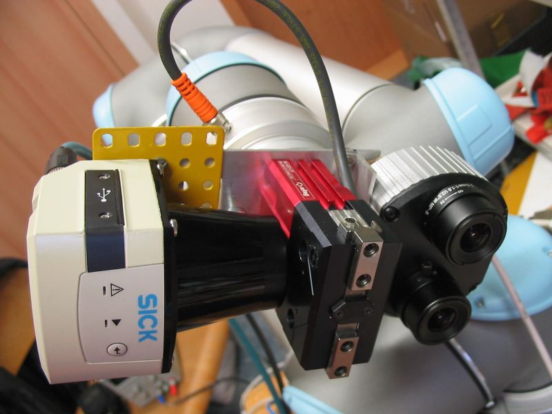
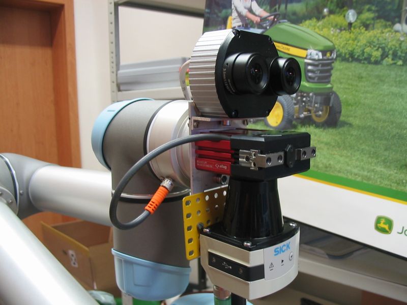
15th December 2014 — PoE IP Camera
Last Tuesday we received new camera for robotic experiments. It is from the
same manufacture as the camera on robot Eduro. It is
compact (half length) and it has two sensors — see
AV3236
specification. The camera is sold for Day/Night surveillance and it has
removable IR cut filter.
When we unpacked it we wondered: where is the power connector? There is none!
There are 4 pins for input/output, but none for separate power. The reason is
hidden in label PoE
(Power over Ethernet).
i.e. the camera is powered by unused lines of Ethernet cable.
You need something like power injector.
AirLive passive PoE
Kit looked good, but when I attached the power (18V, 24W) it did not work
:-(. I supposed that the camera is for wide range 12V-30V(?) like the
previous one, but it is not. PoE and Auxiliary Power: 12-48V DC/24V AC
(Auxillary Power Not Available for Dual Sensor Model). You need PoE
standard voltage which means 48V. The camera is still working on 32V (that is
the very edge), but 48V is the recommended voltage.
I have seen first H264 video and some pictures from this sensor, but I do not
have the power adapter now to run it and show it you too — so at least some
photos:


16th December 2014 — Dual Sensor
Now only a quick info about camera status. I bought 48V power adapter and when
I connected power to injector and Ethernet cable to camera it did not work.
Again. Or to be precise there is not way of telling if it is working or not.
The LED for Ethernet will start to blink only when Ethernet cable is also
connected on the other side (to router or laptop). So make sure you have
connected everything and then it works. Fixed.
The second issue was IP address of the camera. If you have Windows OS then
probably the simplest way is to install AV200 Software and click and click.
The good news is that old command/URL to get JPEG image is still working:
http://192.168.1.6/img.jpg
Which sensor is used depends on your settings. Default is Automatic (for
bright light it is using Day sensor and for darkness Night sensor),
then Day, Night and Dual Channel Streaming. Here are first pictures
for day and night manual setting:


So it looks like the left eye is for night mode. The next step would be
to test streaming of both sensors — I am curious if there is still a chance
to extract individual images from both sensors. We will see (later today at
school).
p.s note, that by default day sensor has resolution 1024x768 and night sensor
640x480
17th December 2014 — 2nd 3D-Scanning Experiment
Yesterday we repeated the 3D scanning experiment.
This time in combination with new camera so we have also reference pictures
with timestamps. Again, there were several new things we learned.
First of all it is the new Dual Sensor Camera AV3236DN. I did not succeed to
automatically record H.264 video streams from both cameras, so fall back was a
single image every 10 scans (see
diff).
It was quite hard to find Camera API. There are several
manuals, papers, presentations pointing to non-existing page :-(. At the end I
found it
here,
but I doubt it is persistent link. Look for
ArecontVisionAPIandCameraWebPageManual6.23.2014.pdf. Here are some
interesting hints:
http://192.168.1.6/livevideo
http://192.168.1.6/h264stream
http://192.168.1.6/h264f
Once I typed h264stream in my browser it generated like 100 windows to save
data — not good. The h264f is shortcut for H264 frame, but I was
receiving I-frames only and no P-frame even when I was changing iframe=0
parameter (OT you can be interested in my
experiments with H264, but it is in Czech only at the moment). So it needs
more calmer time for investigation and that was not yesterday.
Another issue we had was related to remission data from laser scanner
TiM55. I remember Jirka was trying to get it work under Linux (see
his
website). The easiest way was to use supported software to enable remission
(checkbox RSSI), and then switch Ethernet cable back to my notebook.
There were extra 3 elements in output array (instead of expected 580 like on
older USB laser scanner there were 583), and now I see on Jirka's page that
"B not defined". Yes:
A9', 'B2', 'B2', 'AC', 'AC', 'AC', 'B2', 'AF', 'AC
', 'A9', 'AC', '0', '1', 'B', 'not', 'defined', '0', '0', '0']
… that's the same problem.
OK, I have to get ready for early morning meeting, so at least some results.
Robotics should be also fun, so thanks Standa for volunteering


Note, there is
minor
change of log2pgm.py in order to handle both range and remission data.
p.s. based on the timestamps of taken images every 10 laser scans it looks like
we really running at 10Hz, but the sensor should support 15Hz, i.e. better
resolution in X coordinate … next time.
18th December 2014 — applethreshold.py
There is new interactive tool on github now:
applethreshold.py.
It is modification of
threshold.py where
I am interested only in narrow space slice. The apple has some expected
size, say 10cm, and in the depth image we can see only front face. This defines
the slice width to 5cm. All other distances are drawn with white color.
The laser scanner is measuring in millimeters and we use division by 5 for gray
conversion, so the 5cm corresponds to integer appleSize=10. Here are two space
slices with apples at 91/2 cm and 98/2 cm distance:


What is it good for? Well, I was not very happy with
brute
force experiment, so I am looking for an alternative solution. This is just a
visualisation tool — the algorithm should look for uniform blobs of given
size.
19th December 2014 — Crazy Ideas
I must be influenced by the book
Naked Sun I am just reading.
There are plenty of Solarian robots working in apple orchards … I was
looking for Christmas present two days ago — a telescopic tool for picking
apples, and I end up on this Czech website about
work
and travel on New Zealand. And then I realized, that I do not have to wait
till September for real apple picking test. There is new world where the
picking season starts at the end of January and continues till April .
Another piece of jigsaw puzzle is EXACTEC, Czech
distributor of Universal Robots. There is
a chance that we will have their UR5 robot for testing for a week. The goal is
version0 i.e. to autonomously find an apple and pick it from the tree
(because of the winter I would be probably rather Christmas tree). And
yesterday I learned that on 20th of January 2015 I should have a presentation
about my future research … so why not to join these two, and present the
first results on the real machine?! Yes, mission impossible, but we are used to
it, right? Did we have more time for any other „competition”? There is one
month remaining (well, half of that are holidays), and it is strong motivation
to win.
So instead of H264 codec I was looking rather on UR5 specs and communication
protocol. Based on the
English manual
there should be Ethernet, which is now probably the simplest way of integration
(both laser scanner and IP camera are connected to the laptop over Ethernet).
Moreover I already found some Python examples how to control the robotic arm
(see
Zacobria
Robot community forum), and it looks like fun. Is it crazy enough?
21st December 2014 — Memories and UR5 API
Yesterday I had no computer day so besides packing of a few Christmas
presents I re-read my very old book about robots (I bought it when I was on
elementary school). The title is
Roboty
slouží člověku (Robots Serves Humans), Surý, Rempsa 1982. I remember that I
was a bit disappointed that time (30+ years ago) and probably did not
understand it very much.
If nothing else it is clear now, why UR5 has
6-DOF (six degrees of
freedom). If you want to be able to hold a tool in given position (x,y,z) you
need 3-DOF. But if you also need 3D orientation (roll, pitch, yaw) then you
need obviously six degrees of freedom .
My second memory, related to robotic manipulators, is connected with
Probabilistic Path Planner
(PPP). In particular I remember talking to
prof. Overmars in 2000 (Eilat,
Workshop on Computional Geometry), when he was explaining unnecessary
movement issues with probabilistic planners with large number of DOFs
(snake-like robots with 20 or even 50 DOFs).
The third memory is relatively fresh. Last year I was playing with hexapod
FireAnt having 25 servos, i.e. 25-DOFs. Each leg had 3
servos and it was necessary to compute leg transition from one position to
another … and the same holds now for UR5 too. So the distinction between
commands moveJ and moveL is clear now .
UR5 API
Position of 6-DOF robot is defined by 6 numbers. In the case of UR5 these
numbers correspond to the angles of each joint. UR is using term waypoint
for this 6-tuple.
Next, if you have a motor, the simplest control curve is to define acceleration
and maximal speed. The speed profile then looks like trapezoid.
OK, so we have waypoints and standard control for motor speed. Now it
starts to be a little bit more tricky. What if you combine two or more
waypoints? Say when you want to move from one position to another? See page 117
of
UR5_User_Manual_GB.pdf:
- moveJ — will make movements that are calculated in the joint space of the robot arm. Each joint is controlled to reach the desired end location at the same time. This movement type results in a curved path for the tool. The shared parameters that apply to this movement type are the maximum joint speed and joint acceleration to use for the movement calculations, specified in deg/s and deg/s2, respectively. If it is desired to have the robot arm move fast between waypoints, disregarding the path of the tool between those waypoints, this movement type is the favorable choice.
- moveL — will make the tool move linearly between waypoints. This means that each joint performs a more complicated motion to keep the tool on a straight line path. The shared parameters that can be set for this movement type are the desired tool speed and tool acceleration specified in mm/s and mm/s 2 , respectively, and also a feature. The selected feature will determine in which feature space the tool positions of the waypoints are represented in. Of specific interest concerning feature spaces are variable features and variable waypoints. Variable features can be used when the tool position of a waypoint need to be determined by the actual value of the variable feature when the robot program runs.
Note, that there exists also moveP, which will move the tool linearly
with constant speed with circular blends, and is intended for some process
operations, like gluing or dispensing.
I suppose, that combination of moveJ and moveL should be enough for
control of applebot-ver0 …
22nd December 2014 — Apple Generators
On Sunday evening I did one more experiment. An apple has shape close to sphere
so the central part has to be closer than the points on the edge. That is what
you should see after this
diff.
 two levels threshold |
Here you can see that the center part the apple is gray while the area around
it black. Note, that this is also true for the pot below.
Then I went back and tried to detect dense areas, i.e. if you have window
10x10 pixels that most pixels are occupied. Note, that all you need to do is
convolution with matrix filled with ones (you have to change image that apple
pixels are 1 while the rest is 0). With
applethrehold.py
you can now see both windows (threshold and dense areas).
The last step was change of dense areas into generator of interesting positions
and integration with the apple sphere matching — see the
diff.
Does it sound/look good? Well, the result is a bit disappointing
 dense areas apple detections |
You see that also the pot and the chair has 3D surface similar to sphere. There
will be probably no such smooth large areas in the outdoor tests, but still
something which should be solved soon.
This is crazy:
winSizeY 4 (271, 380, 3)
1.00: (0.034, 0.847, -0.035) 0.085
so this part of chair fits 100%?! There is narrow window because of the 0.899m
distance, but … I can add there also the upper limit — not all point should
fit perfectly. It is projection of sphere with bounding rectangle. Expected fit
is given by area, i.e. for radius=1 is the area PI and square is 2x2 =
math.pi/4. = 0.7853981633974483.
Here is result with upper limit:
 upper limit for fitting sphere points |
and here is the
code
change. There is still problem on the border (and always will be), and also
the tolerance to apple view blocking leaves is lower.
4th January 2015 — Recording H264 video
Well, I was a bit sick last two weeks … I was not obviously following
recommendation: An apple a day keeps the doctor away . It is still not
very good but I miss playing with Applebot .
I would start with experiment with the new camera today. You can find now
on github simple script
dualcam.py,
which is recording H264 video stream. I was actually very close to the
working solution. The missing parameter was ssn — stream identifier.
If you do not specify it you will always get I-frames only.
http://192.168.1.6/h264f?res=half&qp=20&ssn=13
http://192.168.1.6/h264f?res=half&qp=20&ssn=13&iframe=0
[SOLVED]
The second task is to enable day and night sensors. It is necessary to enable
given input:
http://192.168.1.6/get?daynight
http://192.168.1.6/set?daynight=dual
and then you can download separately color or monochrome images:
http://192.168.1.6/image?channel=mono
http://192.168.1.6/image?channel=color
Here
is the first attempt to set the mode and record H264 video … but it does not
work, so far. If I use day or night mode then video stream is OK. But
if I select dual then channel=color and channel=mono does not seems
to have any influence. Maybe mix with ssn?
9th January 2015 — stereo_match.py
Almost two weeks ago I was playing with following idea: If I have several
images collected from linear motion, I should be able to get some stereo vision
results?! … and sure enough there is directly example in OpenCV2 (see hint
from
stackoverflow).
It is necessary to slightly modify the stereo_match.py source code, that it
will read your images instead of prepared demo (BTW the source was in my case
in c:\opencv\sources\samples\python2\stereo_match.py) and as result you
will get scene of polygonal patches in
PLY format.
Note, that you can open it with already mentioned
CloudCompare and you will get something like
this:
 Stereo Apple |
… unfortunately the static image is quite boring. If you view it in 3D you
can well recognize the shape of pot, two apples and also small citrus in front
.
11th January 2015 — matplotlib
The topic today was supposed to be debugging laser apple, as I was trying
to find out what is going on in the apple 3D recognition from the laser scans.
There were bits I expected, like blended borders when readings on the edge
of apple are non-sense. They correspond to some averaging of distance to the
apple and distance to the background. Other details were not expected as for
example variation of laser readings.
At first I wrote a simple
cutting utility,
which is based on OpenCV2 sample mouse_and_match.py. You can click on the
image, select rectangle and then do something with cut patch. Current version
opens extra window with 16x times zoomed image and dumps gray values for
displayed image. The latest version dumps also data of the original laser scan
and its corresponding remission. For more details see
cutter.py
history.
So now I can see the numbers. There are only a few of them — even for an
apple 30cm from the scanner I got like 8 readings, which corresponds to
approximately 4cm in height … strange, I expected more apple-related
readings.
The second surprise was how bad the reading were. There were jumps like 2cm on
the surface of the apple! I tried to visualise it and that's the moment when
matplot comes into the game. After installation on
Win7 I had also install six,
dateutil and
pyparsing, but that was surely
worth it .
Here is the first plot for the laser scans of the apple:

The Y-axis is distance in millimeters and you can see for example on the red
plot 1cm oscillations. This is maybe a better visible on the graph with
artificial offset 1cm for each plot:

And one more graph, when for both axis correspond to distances in
millimeters:

The artificial offset was set to 5mm here in order to fit all plots in the
image. Do you see the plots as approximation of various semi-circles? Well,
maybe …
16th January 2015 — The First Tests with Universal Robot UR5
Yes! Believe it or not we have now the robotic arm UR5 from Universal
Robots. Just for a week (for the Tuesday Jan 20th show), but still it is a
great!
I am currently exhausted and still sick and I should go home, but I am waiting
for completion of devices download for
SOPAS,
which I need only to change IP address of our laser scanner :-(. We already
did it some time ago, but it was probably not saved so now it works on
169.254.225.156, which is not very useful when camera, robot UR5 and my laptop
run all on 192.168.1.x network … just to be patient, which is hard for me
now.
So where are we? We have the robotic arm working = it scans, goes to desired
position, close the gripper, returns home. Smoothly, nicely . If you would
like to see the code, it is on github under
ur5.py.
Camera is recording, so there should not be any problem.
Laser is an issue now. First the IP but also the mounting has to be revised.
There are very bulky cables and the first version of the gripper with sensors
did not take into account wide radius of the arm.
Time to go home …


… at home …
On the way home I was thinking about several steps we already completed, but I
did not mention them. I am more relaxed now so it should be easier to do the
revision:
Inverse kinematics
Well, it was not necessary to do ANY computations . There is magic p
prefix to coordinates send to UR5 so if you send for example:
movej( p[0.139, -0.065, 0.869, -1.311, 1.026, -0.869] )
then the parameters are not angles in radians but they are x, y, z, rx, ry,
rz instead. And because we need angles fixed for version 0 there is no need
to worry what exactly rx, ry, rz means. You just turn the wrist to the
orientation you need and change only the first three parameters x, y, z.
Server vs. Client
When we visited Exactec I learned that the UR5 is
so universal that it also supports many types of communications including one,
where the robot is only a slave/client. You can open sockets to other servers,
run several threads etc. I am glad that also the other way works, i.e. I use
UR5 as server and my notebook is client sending requests. For this kind of
communication is dedicated port 30002. Note, that you can change IP address of
the robot, but it is highly recommend to reboot the robot after this action
. After reboot it worked.
Status Info
I was wondering how to get regular update about current robot joints position
and it turned out that all you need to do is listen . There is a binary
protocol containing 1247 bytes per packet, where you will find everything from
positions, targets, speeds, Cartesian coordinates, voltages, currents,
temperatures …
At the moment I am using only absolute speed of all joints as terminal
condition (reached desired position).
Logging
I fixed my mistake that in Liberec I did not have logging ready. Because we
forgot there power cable (do not laugh ) I was using only bits remaining in
my console. Now I have almost 100 files from today testing, so crack what
is 64bit timestamps should be trivial. And it was (see
diff).
So it is probably time in milliseconds since reboot. The differences are like
12-13ms, i.e. update is approximately 80Hz (???). I will have to measure
absolute time as reference tomorrow.
17th January 2015 — UR5 Video
Here is the first video with UR5 with camera and laser scanner in the
„hand”:
The corresponding demo code commit is
here.
You may notice couple details: first of all the laser scanner is rotated by 180
degrees. There is the yellow Merkur part (something like Mechano), which was
quick and dirty solution, but it works:

|
|
|
I quite like it for rapid prototyping .
Second, the hand does not look like on pictures with Merkur above. I was getting
several times protective stop, position deviates from path Wrist1 until I
realized that the hand is actually self-colliding!

The solution was to change all three joints to this configuration:

What was interesting that X,Y,Z as well as rotation angles were the same as
before! Well, I was warned but you do not quite believe it until you see it
. So letting robot solve inverse kinematics is good, but there could be more
than one solution and only the joints space defines the robot pose
unambiguously!
What else? You can hear the clicking sounds near the apple, as the robot is
trying to pick it and then to drop it. I repeated the test six times and in
four attempts the gripper did not work?! I am not sure if the command was lost
or what was the problem? So one task is to review UR5 output stream if the I/O
is confirmed. It is nice to have all the log files (sent commands included)
where you can see that in all tests the gripper was supposed to close and
open.
Well, I do not see anything in Tool Data, except small current change at
one moment
(diff).
There are also some Masterboard Data
(diff),
and I/O bits changed from ['0x20000', '0x0'] to ['0x10000', '0x10000'] … hmm,
interesting. Yes! I checked the second log file and the bits did not change.
Just double check that it worked in 6th test … yes . OK, so it is probably
necessary to verify these bits and repeat the command until they change.
There was an interesting moment when my Ethernet cable was accidentally
disconnected. UR5 stopped to talk to me. It looked like that it is necessary to
send some command to UR5 first and the it starts to send the data again.
I did not mention that the video is fake!!! — if you followed the github
link you would see it, but who would do that, right? The data collection
was running so you can see me recording the video:

The laser was running all the time so top-down scan corresponds only to part of
this distance map image:
 Distance image from laser scanner |
Do you see there the apple with cable? In the last experiment I moved away
my notebook and I slowed the scanning 4 times (original speed was 0.1m/s). One
pixel corresponded to 1mm (laser has update 10Hz) and after change to 1/4th …
do you see the difference?
 4times slower scan |
I would guess that it is only two times slower, but the log file should clear
this up.
p.s. timestamp 14000-8547=5453 corresponds in reality to 43 seconds (images
pic_150117_132421_000.jpg to pic_150117_132504_039.jpg), so 1 step = 8ms???
Strange. Based on the size of log file the update looks like 20Hz. Maybe some
other documentation will clear this up.
p.s.2 now I should uncomment the
apples = findApples( APPLE_SIZE, scan ) and see what would real detector return + do
transformation to 3D with some offsets …
20th January 2015 — Applebot UR5 ver0
It is working now — see corresponding
diff.
It is not perfect as recorded fake over weekend, but it does the work
autonomously:
- scan the scene
- search for the apple in recorded 3D data
- compute desired 3D pose
- navigate hand towards the apple
- close gripper
- move towards drop zone
- open gripper
I started to record from both cameras and as you can see I had a witness last
night:

Note, that it is not perfect yet. In particular it is necessary to calibrate
rotation around Z axis. I used only 3D offset and that is not sufficient.
Slight rotation of the scanner + imperfect mounting is probably source of
couple centimeters error, which depends on the position on the table (BTW
thanks Milan for nice „apple holder”).
The algorithm is quite simple now. It is using dual threshold defined by apple
size and scans with 5mm step from 20cm to 50cm. It looks only for objects
(contours) of expected size (area parametrized by motion step and distance) in
given 3D slice. Only the first occurrence is accepted now (for higher
reliability for the today's demo).
If you see it working you may find it trivial, but it was a bit „jumpy road”
towards this intermediate goal.
Over weekend I was reading about similar apple harvesting projects, and I
read the Chinese article again. Why did they use 9kg SICK LMS211, with so
bad accuracy (10mm +/- 15mm)?! Well, it was not so bad — the TIM551 has
Systematic error +/- 60mm and Statistical error +/- 20mm! So the fact
that I had problem recognize smooth 3D sphere shape in 3D cloud from small
patch is expected. :-(
I also checked specs of our first scanner LMS100 (from
SICK Robot Day 2010) and it promise
Systematic error ± 30 mm and Statistical error ± 12 mm. Also it can
scan at 50Hz scanning frequency with 0.25 degree resolution. The bad news is
weight 1.1kg without cables and operating range starting from 0.5 meter. So we
will probably stay with the smaller TIM551. On the other hand maybe it is just
a typo, as TIM551 has operating range from 0.05 meter and we used LMS100 mostly
in this close range — see
data
sheet.
This remains me the issue with scanning frequency of TIM551. It should be 15Hz,
but I was getting 10Hz only. Sure enough it is mine fault, due to historical
reasons. It was probably not possible to switch LMS100 to scanning frequency
10Hz, so we had to add there sleep (see Eduro
laser.py code).
So by removing this sleep we may get now 50% faster scanning rate .
Another eyeopener was with UR5. Do you remember my comment that I would expect
the apple from the 6th test on Saturday much bigger (4 times) then in previous
experiments? Well there is a global slider named Target Speed Fraction,
which is probably used mainly in manufacturing, where you first test your
assembly line in slow motion and then you increase to 100%. I was operating the
arm with touch screen control, so I set it to slower speed (41%). But this
control influences also external commands! So in reality I was not scanning
with speed 0.1m/s but rather 0.041m/s. For the last (6th) test I first rebooted
all machines, just to be sure, so this slider was back on 100% and slow speed
0.025m/s was in reality just approximately 2 times slower then in the first
test .
 Shadow Robot Hand |
24th January 2015 — The Hand
I went across this article
last weekend when I was preparing my presentation. It is about space research
but see the picture! And believe it or not it is not science fiction . You
can contact Shadow Robot Company and get quote
for their robotic hand. I was interested in combination with UR5 and they offer
even this combination (also with UR10). Options are left/right hand but also
Lite Hand, which would be the option to combine with UR5. The "normal" hand
weights 4.3kg, which is very close to UR5 payload (5kg) while the "lite"
version is 2.4kg only.
As you would expect it is not cheap toy. But if you take into account that you
can control all part of all fingers and you have force feedback … one day I
would like to test it .
25th January 2015 — Standa and UR5
This is a video recorded shortly before we packed UR5 back into the box. Standa
wanted to try to program it from control panel and you can see that he was more
successful than me with autonomous navigation . Note, that all sensors were
running, in particular you can see TIM551 scanning which you would not see
with bare eye.
30th January 2015 — The Others (part1)
According to a nice survey article Harvesting robots for high-value crops:
state-of-the-art review and challenges ahead, Bac, Henten, Hemming, Edan,
Journal of Field Robotics (2014) … performance of harvesting robots did
not improve in the last three decades and none of these 50 robots were
commercialized. (A project was included in the review if and only if a
complete functional system was built and reported in an English written
conference paper or peer-reviewed journal article.)
Well, that is a bit discouraging. There were only five (!) project for apple
harvesting and from them only two robots were autonomous. It is possible that
situation changed last year or that some project was not published or authors
overlooked it, but still … I expected more projects.
The first presented autonomous apple harvesting robot (AAHR) is from Belgium
and you can read about it in popular article for example
here
and here is scientific paper.
I was told that the robot worked well, but the remaining problems were
increasing productivity, ensuring safety (according to standard regulation in
open field), and the price bringing it to the market. There was in the end no
company willing to take the risk. At the moment there is new group continuing
on the work in this research area.
The second presented AAHR is from China
Design and
control of an apple harvesting robot, but I did not track that path yet.
There is new promising 2014 project on New Zealand — see this
article.
A new startup company with already successful kiwi harvesting robot was
supported by government to commercialize the technology, and the goal is also
to pick apples. The project just started and it is for 4 years.
Finally note for myself , that all we tried to present with our experiment
here I found yesterday in 15 years old article:
A
vision system based on a laser range-finder applied to robotic fruit
harvesting. The laser technology was not so widespread that time but they did
very nice work in recognition of partially occluded spherical fruits. The
inputs were distance and reflectivity measured by laser scanner.