Introduction of teams
Raptors, Quadrons, WallE, ...
There are 14 teams registered for Robotour 2016 in Deggendorf Germany. That is nice start of the second contest decade . Also note, that Robotour is no longer Czech domain — there are 5 teams from Germany, only 4 teams from Czech republic, 2 from Poland, 2 from Slovakia and 1 from Switzerland. In particular I am pleased that there are 5 new teams and even old teams upgraded their robots, sensors, software …
Teams
YouTube playlist of all registrations 2016
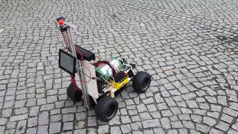
AmBot (CZ)

|
youtube https://youtu.be/HnTYwTIg1NQ
Robot Ferda for Robotour 2016 is a modified children's electric car
("ride-on"). The controller (based on Arduino with ATmega2560) controls
the motors, utilizes magnetometer as a compass, manages three sonars to
detect obstacles, reads data from an external GPS receiver and
communicates with a Bluetooth converter (to respond to commands from the
master system). The master system is an Android smartphone with special
application (RoboNav) for GPS navigation by the map (derived from
OpenStreetMap) supplemented by visual navigation according to smartphone
camera (for keeping on the road).
ARBot (CZ)

|
youtube https://youtu.be/sW_2RUfSADQ
Robot is controlled via Zedboard with SoC Zynq 7020 manufactured by Xilinx.
It has 512 MB RAM, 32 GB SD, the heart is dual-core ARM Cortex A9 +
NEON at 600 MHz and it contains programmable gate array with 85 thousands units.
Zedboard runs on Linux and as main programming language is used mono and C#.
The chassis is differentially driven with 3rd passive wheel. The modeller
wheels have diameter 17 cm and two motors PG36555126000-50.9K with encoders are
controlled by professional unit SDC2160 by Roboteq and it provides necessary
traction.
There are two optical odometers ADNS 3080 for further position improvements.
The next sense is „touch”. Robot has two tactile FSR sensors integrated in
the front bumper.
Time-tested AHRS VN-100 from VectorNav provides information about robot orientation.
The global position information is handled by GPS uBlox NEO 7M.
Robot has two sonars HC-SR04, which can be rotated via model servo motor.
The control unit for model servos is SSC-32.
The robot will use logitech c920 this year.
The energy source are 4 LiFePo cells with capacity 14.5 Ah and protected by
SBM.
The chassis is built from 2mm thick plywood for air models and spruce beams 7
mm. Simply model domain. All parts were cut by laser.
Cogito (CH)

|
youtube https://youtu.be/sVGSWT-eOoc
She was nice and she was beauty,
she was smart and she was fine,
just in one word, she was cutie,
and her name was Clementine.
… all of it with a differentially driven platform, industrial laser
scanner, home-made laser scanner, stereo camera, GPS and compass, highly
modular message passing software architecture with computer vision and
probabilistic localization … simply irresistible.
Istrobotics (SK)

|
youtube https://youtu.be/Jt5gbtevDCA
The base of the robot is modified RC model TRAXXAS E-MAXX (3903) equipped with
webcamera, GPS, sonars HC-SR04, IMU with 3D compass and magnetic IRC. This year
we will give a second chance to RPLIDAR. The control of the robot and basic
sensors is processed via Arduino mega. Image processing and navigation handles
Odroid XU4. Robot is programmed in C++ and OpenCV.
JECC (DE)

|
Hardware:
- Industrial COM Express computer with 6th gen. Core i7, 8GB RAM, 64GB Flash
- GTX960 Graphics Card processing Deep Neural Networks and stereo vision
Custom Software using:
- Qt
- OpenCV
- Caffe
Kamaro Beteigeuze (DE)

|
youtube https://youtu.be/ledYvBy0-bM
Four wheels, axle independent steering, offroad suspension.
x86 PC, ARM Mikrocontrollers, CAN Bus and Ethernet.
Lidar (front/rear) GPS, 9-DOF-IMU, Cameras
ROS-Based Software
Lois, JECC (DE)

|
HARDWARE:
- Raspberry pi 3 with Ubuntu Mate 16.04
- Obstacle recognition with SICK PLS Laser-Scanner
- Motor control via AVR-Mikrocontroller
- Optical odometer
- BNO055-Sensor
SOFTWARE:
- Programmed in C/C++
- Navigation via patched Navit-Software
MART (CZ)

|
The robot chassis is composed of two independent halves connected with axes.
This is mainly to handle complex terrain. The wheels are driven by
industrial stepper motors and each two are connected via toothed belt. The
robot is differentially driven. Motors are controlled over CAN bus. Power
provides two gel Pb accumulators from UPS. Robot is controlled by duo of
BeagleBone Black boards. They integrated inertial unit, compass, GPS and
sonars. There is a special trailer designed for barrel transportation.
No! This is Patrick! (DE)
|
The main hardware consists of a Congatec TS180 COM Express module. For
the main processing, it communicates with the XBox One Kinect and the
Rasberry Pi and displays the crucial information on a Krämer V-800
Touchscreen.
A Raspberry Pi reads the sensor values from the GPS and the Bosch BNO055
and transmits them to the Congatec module. It receives the steering and
speed values from the Congatec module, which are transmitted to the
Freescale KL25Z microcontroller, which in turn controls the RC-Car
model(1:5) via PWM signals.
Quadrons (PL)
|
youtube https://youtu.be/cQRcvG4eTOY
MECHANICS:
Quadron is a quadricycle (ultimately) autonomous mobile robot. It’s
mechanical construction has the car-like kinematic configuration, which
means that on the front axle there are two steering wheels, while the
rear rigid axle is used to propel the vehicle (2WD). The base of the
structure has become an electric quad, produced by Lifestyle-4-U GmbH.
The assumption was to create universal platform, which will be used in
many independent fields and disciplines. That is why we have introduced
a number of electrical and mechanical modifications, especially in the
supporting frame. After changes our robot gained the possibility of
transporting elements of a fairly large scale, because in border cases
up to 60kg, at curb weight of about 60kg. Then we adjusted the drive
systems and steering mechanisms, that could be done with electric
motors. For the movement of the vehicle corresponds 500W DC motor, while
for the movement of the steering wheel is responsible DC gear motor and
coupler system. Each engine was equipped with a driver, encoders and
security features.
ELECTRONICS:
The robot is equipped with a number of sensors and modules responsible
for security, location and orientation in the field. On board are:
- Emergency stop
- Encoders with IMU sensor to determine the position and orientation
- GPS module which allows to set correct position of the vehicle
- SICK 2D laser scanner and ultrasonic sensors located on the front of the vehicle which allows to see what is in front of robot
- Vision system to assist control
- Power supply 3x12V batteries, in order to achieve necessary voltage levels.
The concept of a multi-layer control required the use of computers at
different levels. For the lower is responsible board Nucleo STM. While
higher layer functions on a PC.
SOFTWARE:
To effectively manage and control the robot, we had to accept the
concept of multi-layer software. We decided that the best solution would
be to use platform ROS (The Robot Operating System). As a result, we
have gained the ability to connect all levels.
The lower is responsible for motor control through higher responsible
for manual control using a wireless gamepad and simple autonomy, up to
the highest layer that collects data from sensors, vision, coordinates
designated route and decides where and how the vehicle is moving.
Over the top layer of completely autonomous work is still in progress,
but we are at an advanced stage.
Radioklub Písek - TCVVI (CZ)

|
youtube https://youtu.be/HwBSFMnEKys
E-liška … is already
traditional robot of Radioklub Písek. There are always some changes or rather
major vehicle rebuilds. This time is Eliška driven by 4x4, with new motor in each
wheel. Reworked is also independent suspension of all wheels including
problematic steering (hopefully finally perfect).
The main control computer is notebook with Intel processor and static harddisk.
Secondary computers for control of various groups are with ARM processor. The
energy is stored in gel-lead batteries. Novelty is loading crane on which we
are currently intensively working. Unfortunately new space arrangement forces
us to do more change then we originally anticipated …
Raptors (PL)

|
youtube https://youtu.be/VuRul6QmGOs
Our rover – called Raptor, consists of about 2000 parts designed by our
team. We have used AutoCad Inventor software in the design process. Our
Robot consists of a couple of modules, that can work quite
independently. The main module is a robot’s body, that houses almost all
of the electronics and batteries. The rover is equipped with 6 wheel
drive system, mounted on the rocker boogie suspension. Batteries provide
energy for 90 minutes continues work and have special compartments with
quick changing mechanism. Our on-board computer system is based on SB-
RIO programed in Lab View environment. We are able to supervise all
useful parameters concerning robot localization and orientation which
make the navigation system. The navigation system runs on independent
software and hardware platform. Dedicated software is written in C++
within the Robot Operating System ROS. Our system runs on multiple
machines with different hardware architectures, file systems and OS but
it is not a problem for ROS. Inertial data is provided by high quality
Inertial Measurement Unit with six degrees of freedom, containing
gyroscope and accelerometer. The sensor’s output is three axis angular
velocity and linear acceleration. Using specialized filters system
computes very accurate orientation. GPS module outputs position data
with one meter accuracy. This data passes through the
raspberry pi 3.The weight of Raptors Rover differs depending on the
configuration, reaching maximum of 50 kg in the most complex version.
At our robot we use several safety systems. Due to any emergency
situation, you could use din style red safety button, with cut off all
active parts of rover or send emergency message from base station.
Moreover we are able to fully separate batteries from any electric
modules of robot, by switching off all switches located at back plate of
chasse
Smely Zajko (SK)

|
HARDWARE
Parallax Motor Mount & Wheel Kit (old one) with speed encoders
2x HB-25 Motor Controller
Sbot board (based on AVR ATmega128, low-level control board, hopefully
soon to be replaced with STM32F103 board)
Panasonic SDR T-50 camcorder
Diamond Multimedia One-Touch Video Capture VC500
Hokuyo
5x SRF-08 (ultrasonic sensors)
GPS NaviLock NL-302U USB SiRF III
Compass with tilt compensation (HMC6343)
AVR ATmega8 (compass driver)
usual usb hub
Power: HAZE HZS 12V 9Ah
handmade wood & aluminium base
red power switch and power circuitry
HK6S remote control console + receiver unit for easier transport
ASUS X552M PC as main controller
SOFTWARE
Ubuntu 16.04 LTS
C++ app developed in Netbeans - https://github.com/Robotics-DAI-FMFI-UK
/smely-zajko
AVRStudio for SBot
ChibiStudio for STM32F103 board
FANN library for training and evaluating Neural Networks
WallE (DE)

|
youtube https://youtu.be/v979YcBIVLQ
The main hardware consists of a Microsoft surface tablet. For the main
processing, it communicates with the XBox One Kinect and the Rasberry Pi
and displays the crucial information on its main screen.
A Raspberry Pi reads the sensor values from the GPS and the Bosch BNO055
and transmits them to the Microsoft Surface. It receives the steering
and speed values from the Microsoft Surface, which are transmitted to
the Freescale KL25Z microcontroller, which in turn controls the
Continuous track model via H-Birdges.
second team of the th-deg
If you would like to somehow support this contest or you have some
comments/question, please use our standard contact form.